Data Center Quantized Congestion Notification (DCQCN) is a hybrid congestion control method. DCQCN brings together both Priority Flow Control (PFC) and Explicit Congestion Notification (ECN) so that we can get high throughput, low latency, and lossless delivery across our AI fabric. In this approach, each mechanism plays a specific role in addressing different aspects of congestion, and together they create a robust flow-control system for RDMA traffic.
DCQCN tackles two main issues in large-scale RDMA networks:
1. Head-of-Line Blocking and Congestion Spreading: This is caused by PFC’s pause frames, which stop traffic across switches.
2. Throughput Reduction with ECN Alone: When the ECN feedback is too slow, packet loss may occur despite the rate adjustments.
DCQCN uses a two-tiered approach. It applies ECN early on to gently reduce the sending rate at the GPU NICs, and it uses PFC as a backup to quickly stop traffic on upstream switches (hop-by-hop) when congestion becomes severe.
How DCQCN Combines ECN and PFC
DCQCN carefully combines Explicit Congestion Notification (ECN) and Priority Flow Control (PFC) in the right sequence:
Early Action with ECN: When congestion begins to build up, the switch uses WRED thresholds (minimum and maximum) to mark packets. This signals the sender to gradually reduce its transmission rate. As a result, the GPU NIC slows down, and traffic continues flowing—just at a reduced pace—without abrupt pauses.
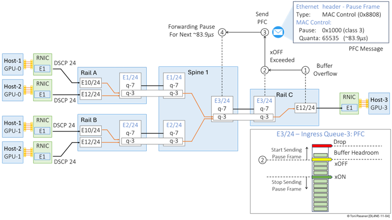
Backup Action with PFC: If congestion worsens and the queue continues to grow, the buffer may reach the xOFF threshold. At this point, the switch sends PFC pause frames hop by hop to upstream devices. These devices respond by temporarily stopping traffic for that specific priority queue, helping prevent packet loss.
Resuming Traffic: Once the buffer has drained and the queue drops below the xON threshold, the switch sends a resume message (a PFC frame with a quanta value of 0). This tells the upstream device it can start sending traffic again.
Why ECN Must Precede xOFF
It is very important that the ECN thresholds (WRED minimum and maximum) are used before the xOFF threshold is reached for three main reasons:
Graceful Rate Adaptation: Early ECN marking helps the GPU NIC (sender) reduce its transmission rate gradually. This smooth adjustment avoids sudden stops and leads to more stable traffic flows.
Avoiding Unnecessary PFC Events: If the sender adjusts its rate early with ECN feedback, the buffers are less likely to fill up to the xOFF level. This avoids the need for abrupt PFC pause frames that can cause head-of-line blocking and backpressure on the network.
Maintaining Fabric Coordination: With early ECN marking, the sender receives feedback before congestion becomes severe. While the ECN signal is not shared directly with other switches, the sender's rate adjustment helps reduce overall pressure on the network fabric.
What Happens If xOFF Is Reached Before ECN Marking?
Imagine that the ingress queue on Spine Switch 1 (from Rail Switch A) fills rapidly without ECN marking:
Sudden Pause: The buffer may quickly hit the xOFF threshold and trigger an immediate PFC pause.
Downstream Effects: An abrupt stop in traffic from Rail Switch A leads to sudden backpressure. This can cause head-of-line blocking and disturb GPU communication, leading to performance jitter or instability at the application level.
Oscillations: When the queue finally drains and reaches the xON threshold, traffic resumes suddenly. This can cause recurring congestion and stop-and-go patterns that hurt overall performance.
By allowing ECN to mark packets early, the network gives the sender time to reduce its rate smoothly. This prevents abrupt stops and helps maintain a stable, efficient fabric.
Figure 11 recaps how the example DCQCN process works:
Time t1: (1) Traffic associated with priority queue 3 on Rail-1’s egress interface 1 crosses the WRED minimum threshold.
Time t2: (2) Rail-1 begins randomly marking ECN bits as 11 on packets destined for GPU-0 on the Host-3.
Time t3: (3) The RDMA NIC starts sending CNP messages to the sender GPU-1 on Host-1.
Time t4: (4) In response to the CNP message, the sending GPU-0 on Host-1 reduces its transmission rate by holding packets longer in its egress queue. (5) At the same time, egress queue 3 on Rail-1 remains congested. (6) Since packets cannot be forwarded from ingress interface 2 to egress interface 1’s queue 3, ingress interface 3 also becomes congested, eventually crossing the PFC xOFF threshold.
Time t5: (7) As a result, Rail-1 sends a PFC xOFF message to Spine-A over Inter-Switch Link 3. (8) In response, Spine-A halts forwarding traffic for the specified pause duration.
Time t6: (9) Due to the forwarding pause, the egress queue of interface 3 on Spine-A becomes congested, which in turn (10) causes congestion on its ingress interface 2.
Time t7: (11) The number of packets waiting in egress queue 3 on interface 1 of Rail-1 drops below the WRED minimum threshold. (12) This allows packets from the buffer of interface 3 to be forwarded.
Time t8: (13) The packet count on ingress interface 3 of Rail-1 falls below the PFC xON threshold, triggering the PFC resume/unpause message to Spine-A. (14) Spine-A resumes forwarding traffic to Rail-1.
After the PFC resume message is sent, Spine-A starts forwarding traffic again toward Rail-1. The congestion on Spine-A’s interface 3 gets cleared as packets leave the buffer. This also helps the ingress interface 2 on Spine-A to drain. On Rail-1, as interface 1 can now forward packets, queue 3 gets more room, and the flow to GPU-0 becomes smoother again.
The RDMA NIC on the sender GPU monitors the situation. Since there are no more CNP messages coming in, the GPU slowly increases its sending rate. At the same time, the ECN marking on Rail-1 stops, as queue lengths stay below the WRED threshold. Traffic flow returns to normal, and no more PFC pause messages are needed.
The whole system stabilizes, and data can move again without delay or packet loss.
Figure 11-7: DCQCN: ECN and PFC Interaction .
DCQCN Configuration
Figure 11-8 shows the six steps to enable DCQCN on a switch. The figure assumes that the RDMA NIC marks RoCEv2 traffic with DSCP 24.
First, we classify the packets based on the DSCP value in the IPv4 header. Packets marked with DSCP 24 are identified as RoCEv2 packets, while packets marked with DSCP 48 are classified as CNP.
After classification, we add an internal QoS label to the packets to place them in the correct output queue. The mapping between internal QoS labels and queues is fixed and does not require configuration.
Next, we define the queue type, allocate bandwidth, and set ECN thresholds. After scheduling is configured, we enable PFC and set its threshold values. A common rule of thumb for the relationship between ECN and PFC thresholds is: xON < WRED Min < WRED Max < xOFF.
To apply these settings, we enable them at the system level. Finally, we apply the packet classification to the ingress interface and enable the PFC watchdog on the egress interface. Because PFC is a sub-TLV in the LLDP Data Unit (LLDPDU), both LLDP and PFC must be enabled on every inter-switch link.
Figure 11-8: Applying DCQCN to Switch.
Step 1: Packet Classification
The classification configuration is used to identify different types of traffic based on their DSCP values. In our example we have one for RoCEv2 traffic and another for Congestion Notification Packets (CNP). The “class-map type qos match-any ROCEv2” line defines a class map named “ROCEv2” that matches any packet marked with DSCP value 24, which is commonly used for RDMA traffic. Similarly, the “class-map type qos match-any CNP” defines another class map named “CNP” that matches packets marked with DSCP value 48, typically used for congestion signaling in RDMA environments. These class maps serve as the foundation for downstream policies, enabling differentiated handling of traffic types. Note that the names “ROCEv2” and “CNP” are not system-reserved; they are simply user-defined labels that can be renamed, as long, as the references are consistent throughout the configuration.
class-map type qos match-any ROCEv2
match dscp 24
class-map type qos match-any CNP
match dscp 48
Example 11-1: Classification.
Step 2: Internal QoS Label for Queueing
The marking configuration assigns internal QoS labels to packets that have already been classified. This is done using a policy map named QOS_CLASSIFICATION, which refers to the previously defined class maps. Within this policy, packets that match the “ROCEv2” class are marked with qos-group 3, and those matching the “CNP” class are marked with qos-group 7. Any other traffic that doesn't fit these two categories falls into the default class and is marked with qos-group 0. These QoS groups are internal identifiers that the switch uses in later stages for queuing and scheduling, to decide how each packet should be treated. Just like class maps, the name of the policy map itself is user-defined and can be anything descriptive, provided it is correctly referenced in other parts of the configuration.
policy-map type qos QOS_CLASSIFICATION
class ROCEv2
set qos-group 3
class CNP
set qos-group 7
class class-default
set qos-group 0
Example 11-2: Marking.
Step 3: Scheduling
The queuing configuration defines how traffic is scheduled and prioritized on the output interfaces, based on the internal QoS groups that were assigned earlier. This is handled by a policy map named “QOS_EGRESS_PORT,” which maps traffic to different hardware output queues. Each queue is identified by a class, such as c-out-8q-q7 (fixed names: 8q = eight queues, q7 = queue number 7). For example, queue 7 is configured with priority level 1, which gives it strict priority over all other traffic. Queue 3 is assigned bandwidth remaining percent 50, meaning that it is guaranteed half of the remaining bandwidth after strict-priority traffic has been serviced. In addition to bandwidth allocation, queue 3 includes congestion management features through the random-detect command. This enables Weighted Random Early Detection (WRED), a mechanism that helps avoid congestion by randomly mark packets as queue depth increases. The minimum-threshold and maximum-threshold define the WRED minimum and maximum values (from 150 KB to 3000 KB) at which packets begin marked. The drop-probability 7 determines the likelihood of packet mark when the maximum threshold is reached, with higher numbers indicating higher marking rates. The weight 0 setting controls how queue size is averaged. A weight of 0 means use instantaneous queue depth (no averaging). Finally, ecn enables Explicit Congestion Notification, allowing network devices to signal congestion without dropping packets, without the ecn option switch drops packet based on WRED min/max values. The remaining queues are configured with either zero percent of remaining bandwidth, effectively disabling them for general use, or with a share of the remaining bandwidth. This queuing policy ensures that RoCEv2 traffic receives adequate resources with congestion feedback, while CNP messages always get through with strict priority.
policy-map type queuing QOS_EGRESS_PORT
class type queuing c-out-8q-q6
bandwidth remaining percent 0
...
class type queuing c-out-8q-q3
bandwidth remaining percent 50
random-detect minimum-threshold 150 kbytes maximum-threshold 3000 kbytes drop-probability 7 weight 0 ecn
...
class type queuing c-out-8q-q7
priority level 1
Example 11-3: Queuing (Output Scheduling).
Step 4: Enable PFC for Queue
The Network QoS configuration defines the low-level, hardware-based characteristics of traffic handling within the switch, such as enabling lossless behavior and setting the maximum transmission unit (MTU) size for each traffic class. In this example, the policy-map type network-qos qos_network is used to configure how traffic is handled inside the switch fabric. Under this policy, the class type network-qos c-8q-nq3 is associated with pause pfc-cos 3, which enables Priority Flow Control (PFC) on Class of Service (CoS) 3. This is critical for RoCEv2 traffic, which depends on a lossless transport layer. The MTU is also defined here, with bytes (jumbo frame) set for class 3 traffic.
policy-map type network-qos qos_network
class type network-qos c-8q-nq3
mtu 9216
pause pfc-cos 3
Example 11-4: Queuing (Output Scheduling).
Priority Flow Control Watchdog
The Priority Flow Control (PFC) watchdog is a mechanism that protects the network from traffic deadlocks caused by stuck PFC pause frames. In RDMA environments like RoCEv2, PFC is used to create lossless classes of traffic by pausing traffic flows instead of dropping packets. However, if a device fails to release the pause or a misconfiguration causes PFC frames to persist, traffic in the affected class can become permanently blocked, leading to what is called a "head-of-line blocking" condition. To mitigate this risk, the priority-flow-control watch-dog-interval on command enables the PFC watchdog feature. When enabled, the switch monitors traffic in each PFC-enabled queue for signs of persistent pause conditions. If it detects that traffic has been paused for too long, indicating a potential deadlock, it can take corrective actions, such as generating logs, resetting internal counters, or even discarding paused traffic to restore flow.
priority-flow-control watch-dog-interval on
Example 11-5: Priority Flow Control (PFC) Watchdog.
Step 5: Bind and Apply QoS Settings
System-level QoS policies bind all the previously defined QoS components together and activate them across the switch. This is done using the system qos configuration block, which applies the appropriate policy maps globally. The service-policy type network-qos qos_network command activates the network-qos policy defined earlier, ensuring that MTU sizes and PFC configurations are enforced across the switch fabric. The command service-policy type queuing output QOS_EGRESS_PORT applies the queuing policy at the output interface level, enabling priority queuing, bandwidth allocation, and congestion management as traffic exits the switch. These system-level bindings are essential because, without them, the individual QoS policies, classification, marking, queuing, and fabric-level configuration, would remain inactive. By applying the policies under system qos, the switch is instructed to treat traffic according to the rules and priorities defined in each policy map. This final step ensures end-to-end consistency in QoS behavior, from ingress classification to fabric transport and egress scheduling, providing a complete and operational quality-of-service framework tailored for latency-sensitive, lossless applications like RoCEv2.
system qos
service-policy type network-qos qos_network
service-policy type queuing output QOS_EGRESS_PORT
Example 11-6: Priority Flow Control (PFC) Watchdog.
Step 6: Interface-Level Configuration
The interface-level configuration attaches the previously defined QoS policies and enables PFC-specific features for a given port. In our example, the configuration is applied to Ethernet2/24, but the same approach can be used for any interface where you need to enforce QoS and PFC settings. The first command, priority-flow-control mode auto, enables Priority Flow Control (PFC) on the interface in auto-negotiation mode. This means the interface will automatically negotiate PFC with its link partner, allowing for lossless traffic handling by pausing specific traffic classes instead of dropping packets. The priority-flow-control watch-dog command enables the PFC watchdog for this interface, which ensures that if any PFC pause frames are stuck or persist for too long, the watchdog will take corrective action to prevent a deadlock situation. This helps maintain the overall health of the network by preventing traffic congestion or blockages due to PFC-related issues. Lastly, the service-policy type qos input QOS_CLASSIFICATION command applies the QoS classification policy on incoming traffic, ensuring that packets are classified and marked according to their DSCP values as defined in the QOS_CLASSIFICATION policy. This classification enables downstream QoS treatment, including proper queuing, scheduling, and priority handling.
interface Ethernet 2/24
priority-flow-control mode auto
priority-flow-control watch-dog
service-policy type qos input QOS_CLASSIFICATION
Example 11-7: Interface Level Configuration.