Wednesday 15 July 2020

BGP EVPN Underlay Network with BGP (Multi-AS)


Introduction


The focus of this chapter is to explain the BGP Multi-AS Underlay Network design in BGP EVPN/VXLAN Fabric. It starts by explaining the BGP configuration because this way explanation can be done by using show and debug command as well as taking packet captures. The next section discusses of BGP adjacency process and its related states (Idle, Connect/Active, OpenSent, Open Confirm and Established). After that, this chapter explains the BGP routing discussing how connected routes are sent from RIB to Loc-RIB and from there to Adj-RIB-Out (Pre/Post). This section also introduces how NLRIs received within BGP Update eventually ends up into the RIB of receiving BGP speaker. In addition, this chapter shortly introduces the MRAI timer as well as a non-disruptive device maintenance solution. The last section tries to give an answer which protocol best fits in the Underlay Network of BGP EVPN fabric.


Infrastructure AS Numbering and IP Addressing Scheme


The AS-numbering scheme used in this chapter is the same as what was used in chapter 1 but instead of using unnumbered interfaces, each inter-switch interface now has an IP address assigned to it. It is possible to use the Unnumbered interface also with BGP using IPv6 Link-Local addressing [RFC 5549]. However, this solution is not supported by all vendors.
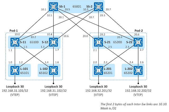

Figure 2-1: IP addressing Scheme.

Tuesday 7 July 2020

BGP EVPN Underlay Network with OSPF

Introduction


The foundation of a modern Datacenter fabric is an Underlay Network and it is crucial to understand the operation of the Control-Plane protocol solution used in it. The focus of this chapter is OSPF. The first section starts by introducing the network topology and AS numbering scheme used throughout this book. The second section explains how OSPF speakers connected to the same segment become fully adjacent. The third section discusses the process of how OSPF speakers exchange Link State information and build a Link-State Database (LSDB) which is used as an information source for calculating Shortest Path Tree (SPT) towards each destination using Dijkstra algorithm. The focus of the fourth section is an OSPF LSA flooding process. It strat by explaining how local OSPF speaker sends Link State Advertisements wrapped inside a Link-State Update message to its adjacent router and how receiving OSPF speakers a) installs information into LSDB, b) Acknowledge the packet, and c) floods it out of OSPF interfaces. The fifth section discusses of LSA and SPF timers. At the end of this chapter, there are OSPF related configurations from every device.

Infrastructure AS Numbering and IP Addressing Scheme


Figure 1-1 illustrates an AS numbering and an IP address scheme used throughout this book. All Leaf switches have dedicated BGP Private AS number while spine switches in the same cluster share the same AS number. Inter-Switch links use Unnumbered IP addressing using (interface Loopback 0) which is also used as OSPF Router-Id. Loopback 0 is not advertised by any device. OSPF type for Inter-Switch link is point-to-point so there is no DR/BDR election process. Leaf switches also have interface Loopback 30 that is used as a VTEP (VXLAN Tunnel End Point) address. Loopback 30 IP addresses are advertised by Leaf switches. All Loopback interfaces are in OSPF passive interface mode. At this stage, all switches belong to OSPF Area 0.0.0.0.


Figure 1-1: AS Numbering and IP Addressing Scheme.