A Guide to Understand the Logic Behind Application Centric Infrastructure
This book will be soon available
Click "read more >>" to open the Table of Contents and see the About the Book section

This book will be soon available
Click "read more >>" to open the Table of Contents and see the About the Book section
This section
explains how to create an object Interface
Profile whose basic purpose is to attach the set of physical interfaces
into this object. Phase 6 in Figure 1-40 illustrates the APIC Management
Information Model (MIM) from the Interface Profile perspective. We are adding
an object L101__102_IPR under the class AccPortP (Leaf Interface Profile). The
name of the object includes Leaf switch identifiers (Leaf-101 and Leaf-102) in
which I am going to use this Interface Profile. This object has a Child object
Eth1_1-5 (class InfraHPorts) that defines the internet block and which has a relationship
with the object Port_Std_ESXi-Host_IPG. By doing this we state that ethernet
interfaces 1/1-5 are LLDP enabled 10Gbps ports which can use VLAN Identifiers
from 300-399. Note that in this phase we haven’t yet specified in which
switches we are using this Interface Profile.
The RN rules used with related objects:
Objects created under the class InfraAccportP (Leaf Interface Profile):Prefix1-{name}, where the Prefix1 is “accportprof”. This gives us RN “accportprof-L101_L102_IPR”.
Objects created under the class InfraHPortS (Access Port Selector): Prefix1-{name}-Prefix2-{type}, where the Prefix1 is “hports” and the Prefix2 is “typ”. This gives us RN “hports-Eth1_1-5_typ-range”.
Objects created under the class InfraPortBlk (Access Port Block): Prefix1-{name}, where the Prefix1 is “portblk” and where the name is Property (autogenerated). This gives us the RN “portblk-Block2”.
This section explains how to create an object Attachable Access Entity Profile (AAEP) that is used for attaching a Domain into Port Group. Phase 3 in Figure 1-20 illustrates the APIC Management Information Model (MIM) from the AAEP perspective. Class AttEntityP is a Child class for infra, and they both belong to packages Infra. I have already added the object attentp-AEP_PHY into the figure. The format of the RN for this object is Prefix1-{name}, where the Prefix1 is attentp. This gives us the RN attentp-PHY-AEP.

Figure 1-20: APIC
MIM Reference: Attachment Access Entity Profile.
This section explains how to create a Physical Domain (Fabric Access Policy). It starts by mapping the REST call POST method and JSON Payload into Fabric Access Policy modeling. Then it explains how the same configurations can be done by using the APIC GUI. Phase 2 in Figure 1-15 illustrates the APIC Management Information Model (MIM) from the Physical Domain perspective. I have already added the object Phys-Standalone_ESXi_PHY into the figure. The format of the RN for this object is Prefix1-{name}, where the Prefix1 is “phys”. This gives us the RN “phys-Standalone_ESXi_PHY”.

Figure 1-15: Fabric
Access Policy Modeling: Physical Domain (click image to enlarge).
Everything in ACI is managed as an Object. Each object belongs to a certain Class. As an example, when we create a VLAN Pool, we create an object that belongs to Class VlanInstP. Classes, in turn, are organized in Packages, Class VlanInstP belongs to Package fvns (fv = fabric virtualization, ns namespace). Figure 1-1 illustrates the classes that we are using in this chapter when we create Fabric Access Policies. Lines with an arrow represent Parent-Child structure and dotted lines represent a relationship (Rs) between classes. We will get back to Rs in becoming sections.

Figure 1-1: ACI Fabric Access Policies.

About this book
The
intent of this book is to explain various design models for Overlay Network and
Underlay Network used in VXLAN Fabric with BGP EVPN Control-Plane. The first
two chapters are focusing on the Underlay Network solution. The OSPF is
introduced first. Among other things, the book explains how OSPF flooding can
be minimized with area design. After OSPF there is a chapter about BGP in the Underlay
network. Both OSPF and BGP are covered deeply and things like convergence are
discussed. After the Underlay Network part, the book focuses on BGP design. It
explains the following models: (a) BGP Multi-AS with OSPF Underlay, this
chapter discusses two design models – Shared Spine ASN and Unique Spien ASN,
(b) BGP-Only Multi-ASN where both direct and loopback overlay BGP peering
models are explained, (c) Single-ASN with OSPF Underlay, (d) Hybrid-ASN with
OSPF Underlay – Pod-specific shared ASN connected via Super-Spine layer using
eBGP peering, (e) Dual-ASN model where leafs share the same ASN, and spines
share their ASN. Each of the design model chapters includes a “Complexity Map”
that should help readers to understand the complexity of each solution. This
book also explains BGP ECMP and related to ECMP, the book also covers ESI
Multihoming. The last chapter introduces how two Pods, can also be geographically
dispersed DCs, can be connected using Layer 3 only DCI with MPLS.
I am
using 5-stage Clos topology throughout the book. Some solutions are though explained
by using only three switches for the sake of simplicity. I am also using
IP-Only Underlay Network with Ingress-Replication, so this book does not cover
Underlay Network Multicast solution. Besides, I am not covering DCI using Layer
2 Border Gateway (BGW) or Overlay Tenant Routing Multicast solution in this
book because those, among the Underlay Multicast solutions, are covered in my first
book “Virtual Extensible LAN – VXLAN: A Practical Guide to VXLAN solution” that
is available at Amazon and Leanpub.
I
wanted to keep the focus of the book fairly narrow and concentrate on the
Control-Plane design and functionality. Please be aware that this book does not
give any recommendation to which solution is the best and which is not. It is
the readers' responsibility to find that out and selects the best solution for
their needs. The book includes 66 full-color images, 260 configuration/show
command examples, and 32 packet captures.
Table of Contents viii
Chapter 1: Underlay Network with OSPF 1
Introduction 1
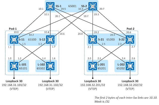
Infrastructure AS Numbering and IP Addressing Scheme 1
OSPF Neighbor Process 2
OSPF Neighbor Process: Init 3
OSPF Neighbor Process: ExStart 7
OSPF Neighbor Process: Exchange and Full 9
Shortest-Path First (SPF)/Dijkstra Algorithm 18
SPF Run – Phase I: Building a Shortest-Path Tree 19
First iteration round 20
Second iteration round 21
Third iteration round 24
SPF Run – Phase II: Adding Leafs to Shortest-Path Tree 25
Convergence 26
Flood reduction with multiple OSPF Areas 30
OSPF summarization in ABR 40
Removing OSPF Router from the Datapath 43
LSA and SPF timers 47
LSA Throttling Timer 47
Flood Pacing Timer 49
LSA Group Pacing Timer 50
Summary 51
References 52
Chapter 2: Underlay Network with BGP 53
Introduction 53
Infrastructure AS Numbering and IP Addressing Scheme 54
BGP Configuration 55
Leaf Switches 55
Spine Switches 56
Super-Spine Switches 56
BGP Neighbor Process 57
Idle 57
Connect 57
Active 57
Finalizing negotiation of the TCP connection 58
OpenSent and OpenConfirm 61
Established 61
BGP NLRI Update Process 65
RIB to Adj-RIB-Out (Pre-Policy) 65
Adj-RIB-Out (Pre) to Adj-RIB-Out (Post) 65
Adj-RIB-In (Post) to Adj-RIB-In (Pre) 66
Adj-RIB-In (Pre) to Loc-RIB 66
Loc-RIB to RIB 66
BGP Update: Unreachable Destination 70
MRAI Timer 71
BGP AS-Path Prepend 71
OSPF and BGP Comparison 75
References 78
Chapter 3: BGP Multi-AS with OSPF Underlay 79
Introduction 79
Inter-Switch Link IP addressing 80
Underlay Network Routing with OSPF 81
Overlay Network BGP L2VPN EVPN Peering 83
Adding L2VN segment 86
Routing comparison: Spine Sharing ASN vs. Unique ASN 88
Spine Switches Sharing ASN 88
All Switches in Unique ASN 94
BGP convergence: Group of Spines in the same AS 101
BGP convergence: All switches in unique AS 106
Complexity Chart of Multi-ASN Design with OSPF Underlay 113
Spines in shared ASN – OSPF Underlay 113
All switches in unique ASN - OSPF Underlay 114
References 115
Chapter 4: BGP Only Multi-ASN Design 117
Introduction 117
Underlay: Direct Peering – Overlay: Loopback 117
Underlay: Direct Peering – Overlay: Direct Peering 125
Complexity Chart Multi-ASN Design with eBGP Underlay 132
Direct Underlay Peering – Loopback Overlay Peering 132
Direct Underlay Peering – Direct Overlay Peering 133
Chapter 5: Single AS Model with OSPF Underlay 135
Introduction 135
Configuration 136
BGP Policy and BGP Update Configuration 136
Leaf Switches 136
Spine Switches 137
Super-Spine Switches 138
Verification 140
BGP L2VPN EVPN Peering 140
BGP Table Verification 140
Inconsistency Problem with Received Route Count 142
Fixing the Problem 148
Re-checking of BGP Tables 151
NVE Peering 154
MAC Address Table and L2RIB 156
Data-Plane Testing 158
Complexity Chart 159
Single-AS Design with OSPF Underlay 159
Chapter 6: Hybrid AS Model with OSPF Underlay 161
Introduction 161
Configuration 162
Leaf – BGP Policy and BGP Update settings 162
Spine - BGP Adjacency and BGP Update settings 163
SuperSpine - BGP Adjacency and BGP Update settings 166
Verification 170
Complexity Chart of Hybrid-ASN Design 186
Direct Underlay Peering – Loopback Overlay Peering 186
Chapter 7: Dual-AS Model with OSPF Underlay 188
Introduction 188
Configuration 189
BGP Adjacency Policy 189
BGP Update Message Modification 189
BGP Loop Prevention Adjustment 190
Verification 192
BGP peering 192
BGP table 192
L2RIB 195
MAC Address Table 196
Complexity Chart of Hybrid-ASN Design with OSPF Underlay 197
Chapter 8: ESI Multi-Homing 198
Introduction 198
ESI Multihoming Configuration 199
Designated Forwarder fo L2BUM 201
Mass-Withdraw 205
Load-Balancing 213
References 216
Chapter 9: ECMP process 217
ECMP process 217
Chapter 10: L3-Only Inter-Pod Connection 227
Introduction 227
MPLS Core Underlay Routing with IS-IS. 228
IS-IS Configuration 229
IS-IS Verification 229
MPLS Label Distribution with LDP 231
MPLS LDP Configuration 233
MPLS Verification 233
MPLS Control-Plane Operation - LDP 235
MPLS Data-Plane Operation – Label Switching 236
BGP VPNv4 Peering 238
BGP VPNv4 Configuration 238
BGP VPNv4 Peering Verification 239
BGP L2VPN EVPN Peering 240
BGP VPNv4 Configuration 240
BGP L2VPN EVPN Peering Verification 241
Adding Tenant to Border Leafs 242
Tenant Configuration 242
Verification 244
Control-Plane: End-to-End Route Propagation 244
Data-Plane: Label Switching Path 249
Data-Plane: ICMP Request 251
Appendix A: Chapter 10 device configurations 253