Priority Flow Control (PFC) is a mechanism designed to prevent packet loss during network congestion by pausing traffic selectively based on priority levels. While the original IEEE 802.1Qbb standard operates at Layer 2, using the Priority Code Point (PCP) field in Ethernet headers, AI Fabrics rely on Layer 3 forwarding, where traditional Layer 2-based PFC is no longer applicable. To extend lossless behavior across routed (Layer 3) networks, DSCP-based PFC is used.
In DSCP-based PFC, the Differentiated Services Code Point (DSCP) field in the IP header identifies the traffic class or priority. Switches map specific DSCP values to internal traffic classes and queues. If congestion occurs on an ingress interface and a particular priority queue fills beyond a threshold, the switch can send a PFC pause frame back to the sender switch, instructing it to temporarily stop sending traffic of that class—just as in Layer 2 PFC, but now triggered based on Layer 3 classifications.
This behavior differs from Explicit Congestion Notification (ECN), which operates at Layer 3 as well but signals congestion by marking packets instead of stopping traffic. ECN acts on the egress port, informing the receiver to notify the sender to reduce the transmission rate over time. In contrast, PFC acts immediately at the ingress port, pausing traffic flow in real time to avoid buffer overflows and packet drops.
PFC relies on two thresholds to control flow: xOFF and xON. The xOFF threshold defines the point at which the switch generates a pause frame when a priority queue reaches a congested state. Once triggered, upstream devices halt transmission of that traffic class. The switch continuously monitors its buffer occupancy, and when the level drops below the xON threshold, it sends a PFC frame with a Quanta value of 0 for the affected priority. This signals the upstream device that it can resume transmission for that specific priority queue.
A key requirement for PFC to function correctly is the provisioning of buffer headroom. The switch must reserve enough buffer space per priority class to accommodate in-flight traffic while the pause frame propagates to the sender and takes effect.
DSCP-based PFC enables lossless packet delivery over routed networks, which is especially important for technologies like RoCEv2 (RDMA over Converged Ethernet v2), where even minimal packet loss can cause significant performance degradation.
DSCP-Based PFC Process over a Layer 3 Routed Interface (Example Scenario)
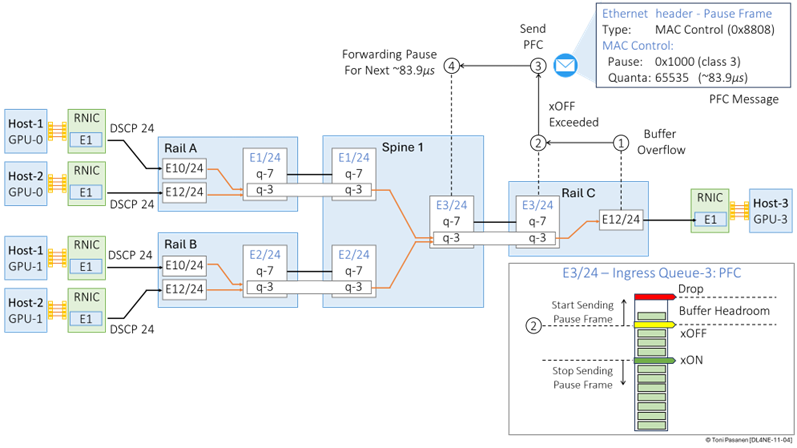
This example illustrates how DSCP-based Priority Flow Control (PFC) operates across a routed Layer 3 fabric during congestion. We walk through a four-step process, beginning with buffer overflow and ending with traffic pausing on the correct priority queue.
Step 1: Buffer Overflow on Rail Switch C (Egress to GPU-3, Host 3)
In a GPU cluster, multiple GPUs are sending high-throughput RDMA traffic to GPU on Host-3. In Figure 11-4 Rail Switch C is responsible for forwarding traffic toward GPU-3. The egress interface on Switch C (E12/24) that connects to GPU-3 becomes congested. Due to the overflow of egress queue 3, packets from ingress queue 3 on interface E3/24 cannot be placed into egress queue 3.
Step 2: xOFF Threshold Exceeded
Priority queue 3 of has two configured thresholds:
• xOFF threshold: Triggers a pause when buffer usage exceeds this level.
• xON threshold: Triggers a resume when the buffer has drained sufficiently.
Once priority queue 3 on ingress interface E3/24 exceeds its xOFF threshold, the switch takes immediate action to prevent packet loss by generating a PFC pause message targeted at the sender. The sender in this case is Spine Switch 1, which is sending traffic to Rail Switch C, over interface E3/24, for delivery to GPU-3.
Step 3: Generating a PFC Pause Frame (MAC Control Frame)
To pause the sender, Rail Switch C generates an Ethernet MAC Control frame with:
• Ethertype 0x8808: This indicates a MAC Control frame, used for pause-related operations (standardized in IEEE 802.3x). Inside this frame, a PFC opcode (0x0101) specifies it's a Priority-based Pause (PFC) message.
• Class Enable Vector (CEV): This 8-bit field indicates which priority queues should be paused. Each bit corresponds to one of the 8 possible traffic classes (0–7). For example, if bit 3 is set to 1, it tells the sender to pause traffic for priority queue 3 only, while all other bits remain 0. In our case, the CEV is 0x1000. Note that the right-most bit represents queue 0.
• Quanta Field(s): For each enabled priority (bit set to 1), a corresponding quanta value is specified. This value defines the duration of the pause, measured in units of 512 bit times.
For a 400 Gbps interface:
• 1 bit time = 1 / 400,000,000,000 seconds ≈ 2.5 picoseconds
• 1 quanta = 512 × 2.5 ps = 1.28 nanoseconds
• If the pause quanta is set to maximum value 0xFFFF (65535), the pause duration is roughly 83.9 microseconds.
This pause frame is sent back to the sender Spine Switch 1. Since the DSCP-based classification maps back to priority queue 3, and the switches share the same mapping, Spine Switch 1 will interpret this correctly.
Step 4: Spine Switch 1 Pauses Transmission on Priority Queue 3
Upon receiving the PFC frame on its ingress interface E3/24 connected to Rail Switch C, Spine Switch 1 examines the class enable vector.
• Since bit 3 is set, the switch knows to pause transmission of all frames mapped to priority queue 3 (DSCP value 24 in our example) on egress interface E3/24.
Traffic for other priority queues continues unaffected.
Spine Switch 1 holds off transmission of priority 3 traffic until it receives a subsequent PFC frame with quanta = 0, indicating “resume,” or a pause duration timeout occurs, after which the switch resumes sending unless another pause is received.
Figure 11-4: Priority Flow Control – Pause
Frame.
The following example shows how Priority Flow Control (PFC) events can cascade upstream when congestion persists in a routed Layer 3 fabric. This scenario builds on the earlier case, where Spine Switch 1 paused traffic to Rail Switch C. Now, we observe how that pause affects traffic originating from Rail Switches A and B.
Step 5: Congestion on Spine Switch 1 Egress Queue to Rail Switch C
As described in the previous figure, Spine Switch 1 received a PFC frame from Rail Switch C and responded by pausing traffic on priority queue 3 on its egress interface E3/24 (towards Rail Switch C). Because this interface is no longer sending traffic, frames destined for GPU-3 via Rail Switch C begin to accumulate in Spine Switch 1’s egress queue 3. This build-up causes backpressure that impacts the ingress side of the switch.
Step 6: xOFF Threshold Exceeded on Spine Switch 1 Ingress Interfaces
Spine Switch 1 receives incoming traffic from Rail Switch A (interface E1/24) and Rail Switch B (interface E2/24). Both switches are sending traffic mapped to priority queue 3 (e.g., DSCP 24). As the egress queue to Rail Switch C becomes full and cannot drain, the corresponding ingress buffers on interfaces E1/24 and E2/24 also begin to fill up, specifically for queue 3. Eventually, the xOFF thresholds on both ingress interfaces are exceeded, indicating that congestion is now impacting the reception of new packets on these ports.
Step 7: Spine Switch 1 Sends PFC Pause Frames to Rail Switch A and B
To avoid dropping packets due to ingress buffer overflow, Spine Switch 1 generates PFC MAC Control frames on both E1/24 and E2/24. The class enable vector has bit 3 set, instructing the sender to pause traffic corresponding to priority queue 3. A suitable quanta value is included to define the pause duration. These control frames travel back to Rail Switch A and Rail Switch B respectively.
Step 8: Rail Switches A and B Pause Queue 3 Traffic to Spine Switch 1
Upon receiving the PFC frames, both Rail Switch A and Rail Switch B interpret the class enable vector and pause all traffic mapped to priority queue 3 (e.g., DSCP 24), still forwarding traffic on other priority queues unaffected. This marks the upstream propagation of congestion: a single bottleneck on the path to GPU-3 can trigger PFC reactions all the way back to multiple source switches.
Figure 11-5: Priority Flow Control – Cascading Effect.
Steps 9a – 14: Downstream Resume and Congestion Recovery
Figure 11-6 illustrates how the PFC-based congestion recovery process extends from Rail Switches A and B all the way to the GPU NICs, while simultaneously resolving the initial congestion at Rail Switch C.
As a result of the earlier PFC pause frames:
• Rail Switch A and Rail Switch B have paused sending priority queue 3 traffic to Spine Switch 1.
• In turn, Spine Switch 1 has paused its own egress traffic toward Rail Switch C on interface E3/24.
This pause allows queue 3 on Rail Switch C’s egress interface E12/24 (toward GPU-3) to drain, as no new traffic is arriving, and the GPU continues to consume incoming data.
Once the buffer utilization for priority queue 3 drops below the configured xON threshold, Rail Switch C initiates congestion recovery.
• It sends a MAC Control Frame (Ethertype 0x8808) back to Spine Switch 1.
• The class enable vector has bit 3 set (indicating priority queue 3).
• The quanta value is set to 0, signaling that it is now safe to resume transmission.
Upon receiving this resume message, Spine Switch 1 can begin sending traffic again on priority queue 3, restoring throughput toward GPU-3 and continuing the flow of RDMA traffic through the network. This recovery mechanism operates consistently across the entire AI fabric.
Figure 11-6: Priority Flow Control – PCIe Bus Congested: Cascading Effect.
LLDP with DCBX
PFC negotiation is performed using the Link Layer Discovery Protocol (LLDP), which carries Data Center Bridging eXchange (DCBX) Type-Length-Value (TLV) structures. At the time of writing, DCBX exists in two versions: IEEE and CEE. The IEEE mode (defined in 802.1Qbb and 802.1Qaz) is standards-based and supported by most modern data center switches from various vendors. This mode is also known as DCBXv2. Some older Cisco Nexus models support only the Cisco/Converged Enhanced Ethernet (CEE) mode. Capture 11-1 shows the packet format of a standards-based IEEE DCBX TLV within an LLDP message.
Capture 11-1: PCF: LLDP with IEEE DBCXv2 TLV .


Hi Toni, i wonder regarding this statement you mentioned "Class Enable Vector (CEV): This 8-bit field indicates which priority queues should be paused. Each bit corresponds to one of the 8 possible traffic classes (0–7). For example, if bit 3 is set to 1, it tells the sender to pause traffic for priority queue 3 only, while all other bits remain 0. In our case, the CEV is 0x1000. Note that the right-most bit represents queue 0." I think that it should be 0000 1000 or 0x08 ..please correct me
ReplyDelete