
Note! This post is under the technical review
Introduction
Virtual Filtering Platform (VFP) is Microsoft’s cloud-scale software switch operating as a virtual forwarding extension within a Hyper-V basic vSwitch. The forwarding logic of the VFP uses a layered policy model based on policy rules on Match-Action Table (MAT). VFP works on a data plane, while complex control plane operations are handed over to centralized control systems. The VFP includes several layers, including VNET, NAT, ACL, and Metering layers, each with dedicated controllers that program policy rules to the MAT using southbound APIs. The first packet of the inbound/outbound data flow is processed by VFP. The process updates match-action table entries in each layer, which then are copied into the Unified Flow Table (UFT). Subsequent packets are then switched based on the flow-based action in UFT. However, if the Virtual Machine is not using Accelerated Networking (AccelNet), all packets are still forwarded over the software switch, which requires CPU cycles. Accelerated Networking reduces the host’s CPU burden and provides a higher packet rate with a more predictable jitter by switching the packet using hardware NIC yet still relaying to VFP from the traffic policy perspective.
Hyper-V Extensible Virtual Switch
Microsoft’s extensible vSwitch running on Hyper-V operates as a Networking Virtualization Service Provider (NetVSP) for Virtual Machine. VMs, in turn, are Network Virtualization Service Consumers (NetVSP). When a VM starts, it requests the Hyper-V virtualization stack to connect to the vSwitch. The virtualization stack creates a virtual Network Interface (vNIC) for the VM and associates it with the vSwitch. The vNIC is presented to the VM as a physical network adapter. The communication channel between VM and vSwitch uses a synthetic data path Virtual Machine Bus (VMBus), which provides a standardized interface for VMs to access physical resources on the host machine. It helps ensure that virtual machines have consistent performance and can access resources in a secure and isolated manner.
Virtual Filtering Platform - VFP
A Virtual Filtering Platform (VFP) is Microsoft’s cloud-scale virtual switch operating as a virtual forwarding extension within a Hyper-V basic vSwitch. VFP sits in the data path between virtual ports facing the virtual machines and default vPort associated with physical NIC. VFP uses VM’s vPort-specific layers for filtering traffic to and from VM. A layer in the VFP is a Match-Action Table (MAT) containing policy rules programmed by independent, centralized controllers. The packet is processed through the VFP layers if it’s an exception packet, i.e., no Unified Flow entry (UF) in the Unified Flow Table (UFT), or if it’s the first packet of the flow (TCP SYN packet). When a Virtual Machine initiates a new connection, the first packet of the data flow is stored in the Received Queue (RxQ). The Parser component on VFP then takes the L2 (Ethernet), L3 (IP), and L4 (Protocol) header information as metadata, which is then processed through the layer policies in each VFP layer. The VFP layers involved in packet processing depend on the flow destination and the Azure services associated with the source/destination VM.
VNET-to-Internet traffic from with VM using a Public IP
The metering layer measures traffic for billing. It is the first layer for VM’s outgoing traffic and the last layer for incoming traffic, i.e., it processes only the original ingress/egress packets ignoring tunnel headers and other header modifications (Azure does not charge you for overhead bytes caused by the tunnel encapsulation). Next, the ACL layer runs the metadata through the NSG policy statements. If the source/destination IP addresses (L3 header group) and protocol, source/destination ports (L4 header group) match one of the allowing policy rules, the traffic is permitted (action#1: Allow). After ACL layer processing, the routing process intercepts the metadata. Because the destination IP address in the L3 header group matches only with the default route (0.0.0.0/0, next-hop Internet), the metadata is handed over to Server Load Balancing/Network Address Translation (SLB/NAT) layer. In this example, a public IP is associated with VM’s vNIC, so the SLB/NAT layer translates the private source IP to the public IP (action#2: Source NAT). The VNet layer is bypassed if both source and destination IP addresses are from the public IP space. When the metadata is processed by each layer, the results are programmed into the Unified Flow Table (UFT). Each flow is identified with a unique Unified Flow Identifier (UFID) - hash value calculated from the flow-based 5-tuple (source/destination IP, Protocol, Source Port, Destination Port). The UFID is also associated with the actions Allow and Source NAT. The Header Transposition (HT) engine then takes the original packet from the RxQ and modifies its L2/L3/L4 header groups as described in the UFT. It changes the source private IP to public IP (Modify) and moves the packet to TxQ. The subsequent packets of the flow are modified by the HT engine based on the existing UFT entry without running related metadata through the VFP layers (slow-path to fast-path switchover).
Besides the outbound flow entry, the VFP layer processes generate an inbound flow entry for the same connection but with reversed 5-tuple (source/destination addresses and protocol ports in reversed order) and actions (destination NAT instead of source NAT). These outbound and inbound flows are then paired and seen as a connection, enabling the Flow State Tracking process where inactive connections can be deleted from the UFT. For example, the Flow State Machine tracks the TCP RST flags. Let’s say that the destination endpoint sets the TCP RST flags to the L4 header. The TCP state machine notices it and removes the inbound flow together with its paired outbound flow from the UFT. Besides, the TCP state machine tracks the TCP FIN/FIN ACK flags and TIME_WAIT state (after TCP FIN. The connection is kept alive for max. 2 x Max Segment Lifetime to wait if there are delayed/retransmitted packets).
Intra-VNet traffic
The Metering and ACL layers on VFP process inbound/outbound flows for Intra-VNet connections in the same manner as VNet-Internet traffic. When the routing process notices that the destination Direct IP address (Customer Address space) is within the VNet CIDR range, the NAT layer is bypassed. The reason is that Intra-VNet flows use private Direct IP addresses as source and destination addresses. The Host Agent responsible for VNet layer operations, then examines the destination IP address from the L3 header group. Because this is the first packet of the flow, there is no information about the destination DIP-to-physical host mapping (location information) in the cache table. The VNet layer is responsible for providing tunnel headers to Intra-VNet traffic, so the Host Agent requests the location information from the centralized control plane. After getting the reply, it creates a MAT entry where the action part defines tunnel headers (push action). After the metadata is processed, the result is programmed into Unified Flow Table. As a result, the Header Transposition engine takes the original packet from the Received Queue, adds a tunnel header, and moves the packet to Transmit Queue.

Figure 1-1: Azure Host-Based SDN Building Blocks.
Policy Programming to VFP
Figure 1-2 provides an overview of process flows involved in creating a new Virtual Network (VNet) and deploying a Virtual Machine (VM) with a Public IP (PIP) in the Azure cloud.
- To begin, an administrator builds two Bicep files, with the first file describing the VNet and its subnets, PIP for VM, and Network Security Group (NSG) with policy rules, and the second file defining the VM itself. The administrator then uses the Microsoft PowerShell tool to deploy the first file.
- Azure Resource Manager (ARM) acts as a centralized resource management service and validates the user's credentials (authentication) so that they have the necessary authorization to deploy all requested resources.
- After successful authentication and authorization, the Resource Manager calls the Resource Provider Microsoft.Network to create the requested resources (VNet, PIP, and NSG), although they are not yet implemented into physical hosts since the VM has not been launched yet
- Next, the administrator deploys the second file. The ARM authenticates and authorizes the user to deploy the new VM into the VNet with the PIP and NSG associated with its virtual Network Interface Card (vNIC). It then calls the Resource Provider Microsoft.Compute to make the implementation.
- At this phase, the VM is launched as a child partition on one of the physical hosts in the requested Availability Zone (AZ). The vNIC of the VM is associated with vSwitch virtual Port (vPort). Next, Host Agent (HA) calls the controllers to program the policies to VFP layers.
- The controller responsible for security policies deploys the NSG policies on the ACL layer. The controller related to Network Address Translation/Server Load Balancing (NAT/SLB) layer creates a rule where the VM’s Direct IP (DIP) is changed to PIP for egress traffic and the other way around for ingress traffic. The controller responsible for VNet associates the port to correct VNet.
- The HA is also responsible for registering the VM to the centralized location service that keeps track of which physical host VMs are running. The registration includes information about the physical location of the VM (VM IP-to-Host IP mapping) and tenant information (VNet Identifier in tunnel encapsulation), among other things. After the mapping information is stored on the database, it is distributed to hosts where the same VNet is implemented.

Figure 1-2: The High-Level View of the Relationship between Resources and VFP Layers.
Accelerated Networking
When processing data flow from/to a Virtual Machines (VM) using software, CPU cycles are required from both the vCPUs allocated to the VM and the physical CPUs attached to the host. To alleviate this burden, a Virtual Filtering Platform (VFP) processes only the first packet of the data flow and switches subsequent packets to the fast path, where policy is applied based on the flow policy programmed into the Unified Flow Table (UFT). While this approach reduces CPU burden, VM networking is still performed using software, and the high CPU load can still cause increased delays and inconsistent jitter, even after switching flows to the fast path. Azure’s Accelerated Networking brings the hardware SmartNIC into the picture to address performance issues.
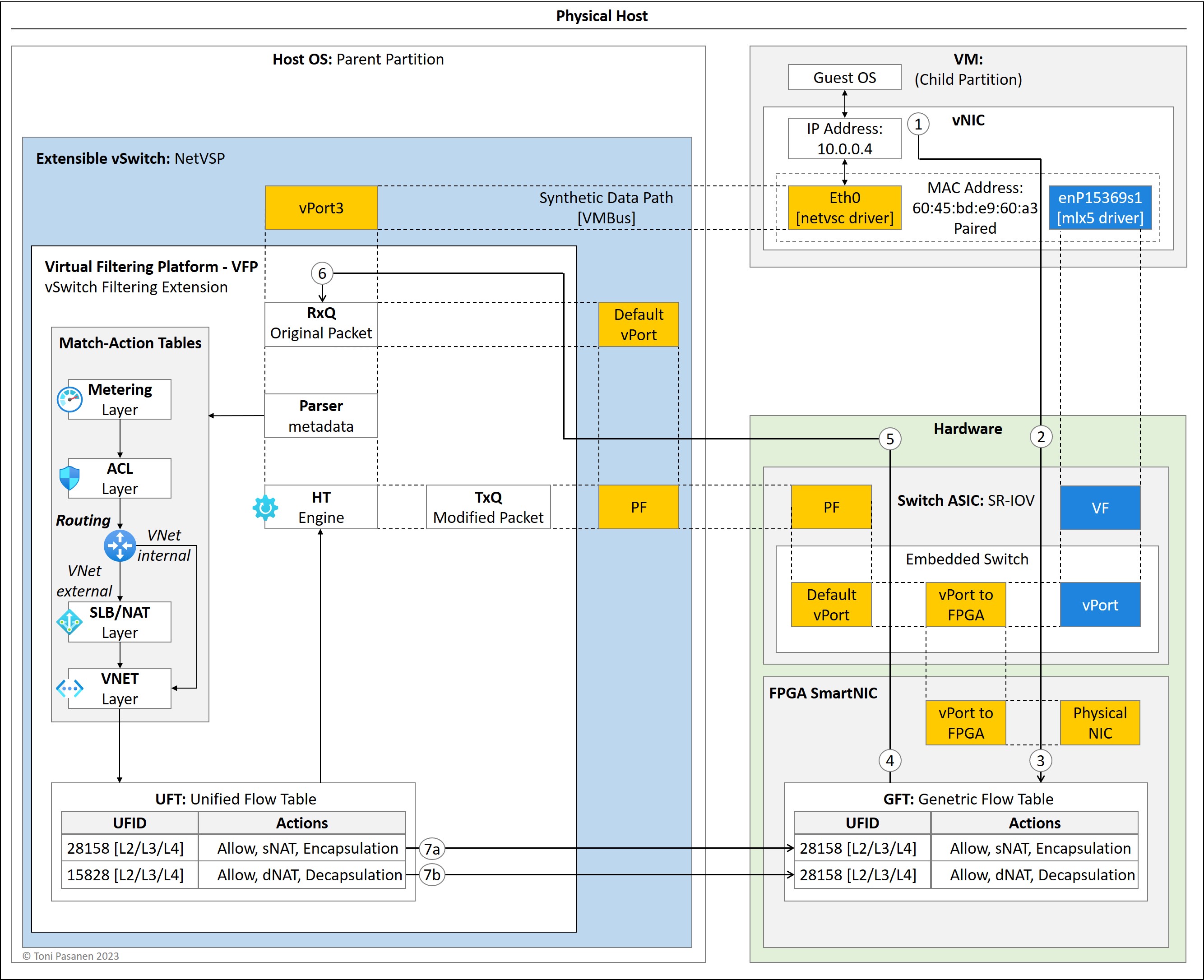
Azure’s Accelerated Networking (AccelNet) architecture still relays on a VFP for creating flow-based actions into the UFT. However, after processing the first packet of the flow, the subsequent packets are switched to the hardware fast path. This decreases CPU load drastically, gives a higher packet rate, and stabiles the jitter. Figure 1-3 illustrates a high-level view of AccelNet architecture. Azure hosts servers have Mellanox/NVIDIA Single Root I/O Virtualization (SR-IOV) hardware NIC, which offers virtual instances, Virtual Function (VF), to virtual machines. When we enable Accelerated Networking on a VM, the mlx driver is installed to vNIC. The mlx driver version depends on an SR-IOV type. The mlx driver on a vNIC initializes a new interface (enP15369s1) that connects the vNIC to an embedded switch on a hardware SR-IOV card. The VF instance appears now to vNIC as a hardware NIC. The new interface enP15369s1 is paired with the Eth0 interface, both associated with the same MAC address. Note that the IP address is published to VMs only by the Eth0 interface. The SR-IOV hardware NIC is connected to an integrated circuit, Field Programmable Gate Array SmartNIC (FPGA SmartNIC), that can be programmed to perform specified logic functions. In Azure AccelNet architecture, the flow entries in Unified Flow Table (UFT) are programmed into the Generic Flow Table (GFT) on FPGA SmartNIC.

Packet Walk
In figure 1-4, we have enabled Accelerated Networking in Virtual Machine. The VM sends outbound traffic flows to the Eth0 interface, where packets are forwarded over the enP15369s1 interface, via SR-IOV NIC to FPGA SmartNIC, where the Generic Flow Table (GFT) lookup is performed. Due to a negative lookup result, the packet is forwarded to VFP for processing. The Parser components take the L2/L3/L4 header information as metadata, which goes through the VFP layers. The flow-action entries for connection are created into the UFT. The result is also programmed into the GFT on FPGA SmartNIC. Subsequent packets are switched based on the flow-based policies in GFT using only the path over a hardware NIC.
Enabling Accelerated Networking
To determine which VM sizes support Accelerated Networking in Azure, you can utilize the Azure VM Comparison service available at azureprice.net. In the basic view, the Accelerated Networking column is not visible, but you can select it from the drop-down menu on the right.

Figure 1-5: Select VM Size Supporting Accelerated Networking.
Accelerated Networking is enabled by default on VMs that support it. Figure 1-6 shows the VM basic image and sizing options with their current monthly costs on the Basics tab. The Accelerated Networking tick box is in the Networking tab.

Verification
References
[1] Daniel Firestone et al., “VFP: A Virtual Switch Platform for Host SDN in the Public Cloud”, 2017
[2] Daniel Firestone et al., “Azure Accelerated Networking: SmartNICs in the Public Cloud”, 2018
[3] What is Azure Resource Manager? “https://learn.microsoft.com/en-us/azure/azure-resource-manager/management/overview”, February 2, 2023
[4] Azure resource providers and types, https://learn.microsoft.com/en-us/azure/azure-resource-manager/management/resource-providers-and-types, August 8, 2022.
[5] https://learn.microsoft.com/en-us/azure/virtual-network/accelerated-networking-overview, December 2, 2022.
[6] https://learn.microsoft.com/en-us/azure/virtual-network/accelerated-networking-how-it-works, December 2, 2022.
[7] https://learn.microsoft.com/en-us/azure/virtual-network/virtual-network-tcpip-performance-tuning#accelerated-networking-and-receive-side-scaling, December 2, 2022
Excellent, very exciting. When you work with azure in daily basis and read such a paper you really feel amazed, thanks and waiting for PaaS based
ReplyDeleteit's amazing the level of low level details about Azure VM networking covered in this article.
ReplyDeleteThe packet walk example was extremely helpful! Seeing how the first packet goes through VFP and subsequent packets switch through the SmartNIC makes the benefits of Azure Accelerated Networking very clear. I’m curious if you’ll also provide guidance on optimizing NSG policies to complement this setup.
ReplyDeleteGood work
ReplyDelete