
Introduction
Remote Direct Memory Access over Converged Ethernet (RoCE) is a transport model that extends InfiniBand semantics over Ethernet networks. It enables direct memory access between hosts by encapsulating InfiniBand transport headers—such as the InfiniBand Transport Header (IBTH) and the RDMA Extended Transport Header (RETH)—within Ethernet, IP, and UDP packets. In by book "Deep Learning for Network Engineers" Chapter 9, describes how RDMA NICs process application work requests, known as InfiniBand verbs, and how these are encoded into IBTH and RETH headers for delivery to remote targets using RoCEv2.
This post shifts focus to the Ultra Ethernet Transport (UET) model, developed by the Ultra Ethernet Consortium (UEC). UET defines an alternative RDMA transport architecture that operates over standard Ethernet networks, without relying on InfiniBand message formats or semantics. While both RoCEv2 and UET enable remote memory access between nodes, UET is not based on InfiniBand transport headers, and the term RoCE is not used in UET systems.
Instead, UET introduces a new Ultra Ethernet (UE) layer composed of several sublayers, including the Semantic Sublayer (SES) and the Packet Delivery Sublayer (PDS). These sublayers are responsible for encoding and transmitting RDMA operations—such as memory addresses, remote keys (RKEYs), operation codes, and completion signaling—over Ethernet. This contrasts with RoCEv2, where such RDMA information is carried within IBTH and RETH headers.
In this chapter, we explore how UET transports data across the Scale-Out Network—a role comparable to the “Backend Network” in RoCEv2-based systems. We will examine how UET supports GPU-to-GPU communication at data center scale, and how its design differs in terms of packet structure, connection setup, and flow control when compared to InfiniBand-based approaches.
This chapter is based on the Ultra Ethernet Specification v1.0, published on June 11, 2025, by the Ultra Ethernet Consortium.
Figure 14-1 depicts a small, two-node parallel computing system, where each node contains two GPUs and UE-capable NIC per GPU. These nodes, along with the Scale-Out Backend Network (Switching Infrastructure), form a cluster. The UEC specification uses the term Fabric Interface (FI) to refer to a UE-capable NIC. In Figure 14-1, all four FIs, together with the leaf and spine switches in the Scale-Out Backend Network, make up the fabric. In this context, the fabric includes all network components: UE-NICs, switching infrastructure, inter-switch links, cabling, and transceivers. One-way delay in Backend Scale-Out Network should be less than 10 µs.
The Scale-Up Network refers to intra-node GPU communication using NVLink and PCIe. Scale-Up Networks can also include short-range interconnects that use a high-speed, low-latency, single-tier (non-CLOS topology) switch—enabling tightly coupled multi-node systems that retain scale-up characteristics. Latency for Scale-Up network should be < 1 µs.
The Packet Delivery Context (PDC), a component of the FEP, is a logical construct responsible for unidirectional packet delivery between two FEPs. The Congestion Control Context (CCC), in turn, manages the transmission rate of traffic exchanged over a given PDC.
The term port refers to the physical port of the UE-capable NIC that connects to a fabric switch. Since multiple FEPs may exist on a single FI—each assigned a unique FA—but the FI may have only one (or two, if dual-homed) physical ports, the FAs of all FEPs on the same FI typically share the same MAC address.
A Fabric Plane is a communication path between two or more Fabric Endpoints (FEPs). In Figure 14-1, two Fabric Planes are shown. Fabric Plane 1 connects FEP 111 and FEP 122 through interfaces E1 and E2 on Leaf Switch 101. Fabric Plane 2 connects FEP 211 and FEP 222 via interfaces E1 and E2 on Leaf Switch 102.
In a RoCEv2-based solution, the Scale-Out Network is referred to as the Backend Network, and the communication paths between processes are called Rails.
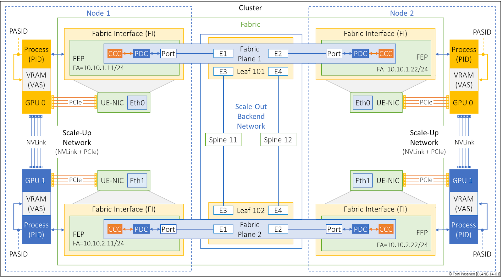
Figure 14-1: Ultra Ethernet
Terminology.
No comments:
Post a Comment