Showing posts with label Ultra Ethernet. Show all posts

Tuesday, 7 October 2025

Ultra Etherent: Discovery

Updated 8-Ocotber 2025

Creating the fi_info Structure

Before the application can discover what communication services are available, it first needs a way to describe what it is looking for. This description is built using a structure called fi_info. The fi_info structure acts like a container that holds the application’s initial requirements, such as desired endpoint type or capabilities.

The first step is to reserve memory for this structure in the system’s main memory. The fi_allocinfo() helper function does this for the application. When called, fi_allocinfo() allocates space for a new fi_info structure, which this book refers to as the pre-fi_info, that will later be passed to the libfabric core for matching against available providers.

At this stage, most of the fields inside the pre-fi_info structure are left at their default values. The application typically sets only the most relevant parameters that express what it needs, such as the desired endpoint type or provider name, and leaves the rest for the provider to fill in later.

In addition to the main fi_info structure, the helper function also allocates memory for a set of sub-structures. These describe different parts of the communication stack, including the fabric, domain, and endpoints. The fixed sub-structures include:

  • fi_fabric_attr: Describes the fabric-level properties such as the provider’s name and fabric identifier.
  • fi_domain_attr: Defines attributes related to the domain, including threading and data progress behavior.
  • fi_ep_attr: Specifies endpoint-related characteristics such as endpoint type.
  • fi_tx_attr and fi_rx_attr: Contain parameters for transmit and receive operations, such as message ordering and completion behavior.
  • fi_nic: Represents the properties and capabilities of the UET network interface.

In figure 4-1, these are labeled as fixed sub-structures because their layout and meaning are always the same. They consist of predefined fields and expected value types, which makes them consistent across different applications. Like the main fi_info structure, they usually remain at their default values until the provider fills them in. The information stored in these sub-structures will later be leveraged when the application begins creating actual fabric objects, such as domains and endpoints.

In addition to the fixed parts, the fi_info structure can contain generic sub-structures such as src_addr. Unlike the fixed ones, the generic sub-structure src_addr depend on the chosen addr_format. For example, when using Ultra Ethernet Transport, the address field points to a structure describing a UET endpoint address, which includes bits for Version, Flags, Fabric Endpoint Capabilities, PIDonFEB, Fabric Address, Start Resource Index, Num Resource Indices, and Initiator ID. This compact representation carries both addressing and capability information, allowing the same structure definition to be reused across different transport technologies and addressing schemes. Note that in figure 4-2 the returned src_addr is only partially filled because the complete address information is not available until the endpoint is created.

In Figure 4-1, the application defines its communication requirements in the fi_info structure by setting the caps (capabilities) field. This field describes the types of operations the application intends to perform through the fabric interface. For example, values such as FI_MSG, FI_RMA, FI_WRITE, FI_REMOTE_WRITE, FI_COLLECTIVE, FI_ATOMIC, and FI_HMEM specify support for message-based communication, remote memory access, atomic operations, and host memory extensions.

When the fi_getinfo() call is issued, the provider compares these requested capabilities against what the underlying hardware and driver can support. Only compatible providers return a matching fi_info structure.

In this example, the application also sets the addr_format field to FI_ADDR_UET, indicating that Ultra Ethernet Transport endpoint addressing is used. This format includes hardware-specific addressing details beyond a simple IP address.

The current Ultra Ethernet Transport specification v1.0 does not define or support the FI_COLLECTIVE capability. Therefore, the UET provider does not return this flag, and collective operations are not offloaded or accelerated by the UET NIC.

After fi_allocinfo() has allocated memory for both the fixed and generic sub-structures, it automatically links them together by inserting pointers into the main fi_info structure. The application can then easily access each attribute through fi_info without manually handling the memory layout. 

Once the structure is prepared, the next step is to request matching provider information using fi_getinfo() API call, which will be described in detail in the following section.

Figure 4-1: Discovery: Allocate Memory and Create Structures – fi_allocinfo.

Requesting Provider Services with fi_getinfo()


After creating a pre-fi_info structure, the application calls the fi_getinfo() API to discover which services and transport features are available on the node’s NIC(s). This function takes a pointer to the pre-fi_info structure, which contains hints describing the application’s requirements, such as desired capabilities and address format.

When the discovery request reaches the libfabric core, the library identifies and loads an appropriate provider from the available options, which may include providers for TCP, verbs (InfiniBand), or sockets (TCP/UDP). For Ultra Ethernet Transport, the core selects the uet-provider. The core invokes the provider’s entry points, including the .getinfo callback, which is responsible for returning the provider’s supported capabilities. Internally, the provider uses function pointers uet_getinfo.

Inside the UET provider, the uet_getinfo() routine queries the NIC driver or kernel interface to determine what capabilities each NIC can safely and efficiently support. The provider does not access the hardware directly. For multi-GPU AI workloads, the focus is on push-based remote memory access operations:

  • FI_MSG: Used for standard message-based communication.
  • FI_RMA: Enables direct remote memory access, forming the foundation for high-performance gradient or parameter transfers between GPUs.
  • FI_WRITE: Allows a GPU to push local gradient updates directly into another GPU’s memory.
  • FI_REMOTE_WRITE: Signals that remote GPUs can write directly into this GPU’s memory, supporting push-based collective operations.
  • FI_COLLECTIVE: Indicates support for collective operations like AllReduce, though the current UET specification does not implement this capability.
  • FI_ATOMIC: Allows atomic operations on remote memory.
  • FI_HMEM: Marks support for host memory or GPU memory extensions.

Low-level hardware metrics, such as link speed or MTU, are not returned at this phase; the focus is on semantic capabilities that the application can rely on. 

The provider allocates new fi_info structures in CPU memory, creating one structure per NIC that satisfies the hints provided by the application and describes all other supported services.

After the provider has created these structures, libfabric returns them to the application as a linked list. The next pointer links all available fi_info structures, allowing the application to iterate over the discovered NICs. Each fi_info entry contains both top-level fields, such as caps and addr_format, and several attribute sub-structures—fi_fabric_attr, fi_domain_attr, fi_ep_attr, fi_tx_attr, and fi_rx_attr.

Even if the application provides no hints, the provider fills in these attribute groups with its default or supported values. This ensures that every fi_info structure returned by fi_getinfo() contains a complete description of the provider’s capabilities and configuration options. During object creation, the libfabric core passes these attributes to the provider, which uses them to map the requested fabric, domain, and endpoint objects to the appropriate NIC and transport configuration.


The application can then select the most appropriate entry and request the creation of the Fabric object. Creating the Fabric first establishes the context in which all subsequent domains, sub-resources, and endpoints are organized and managed. Once all pieces of the AI Fabric “jigsaw puzzle” abstraction have been created and initialized, the application can release the memory for all fi_info structures in the linked list by calling fi_freeinfo().


Figure 4-2: Discovery: Discover Provider Capabilities – fi_getinfo.


Note: fields and values of fi_info and its sub-structures are explained in upcoming chapters

Next, Fabric Object... 


Tuesday, 30 September 2025

Ultra Ethernet: Completion Queue

Completion Queue Creation (fi_cq_open)


Phase 1: Application – Request & Definition


The purpose of this phase is to define the queue where operation completions will be reported. Completion queues are used to report the completion of operations submitted to endpoints, such as data transfers, RMA accesses, or remote write requests. By preparing a struct fi_cq_attr, the application describes exactly what it needs, so the provider can allocate a CQ that meets its requirements.


Example API Call:

struct fi_cq_attr cq_attr = {

    .size = 2048,

    .format = FI_CQ_FORMAT_DATA,

    .wait_obj = FI_WAIT_FD,

    .flags = FI_WRITE | FI_REMOTE_WRITE | FI_RMA,

    .data_size = 64

};


struct fid_cq *cq;

int ret = fi_cq_open(domain, &cq_attr, &cq, NULL);


Explanation of fields:

.size = 2048:  The CQ can hold up to 2048 completions. This determines how many completed operations can be buffered before the application consumes them.

.format = FI_CQ_FORMAT_DATA: This setting determines the level of detail included in each completion entry. With FI_CQ_FORMAT_DATA, the CQ entries contain information about the operation, such as the buffer pointer, the length of data, and optional completion data. If the application uses tagged messaging, choosing FI_CQ_FORMAT_TAGGED expands the entries to also include the tag, allowing the application to match completions with specific operations. The format attribute essentially defines the structure of the data returned when reading the completion queue, letting the application control how much information it receives about each completed operation 

.wait_obj = FI_WAIT_FD: Provides a file descriptor for the application to poll or select on; other options include FI_WAIT_NONE (busy polling) or FI_WAIT_SET.

.flags = FI_WRITE | FI_REMOTE_WRITE | FI_RMA: This field is a bitmask specifying which types of completions the application wants the Completion Queue to report. The provider checks these flags against the capabilities of the domain (fid_domain) to ensure they are supported. If a requested capability is not available, fi_cq_open() will fail. This allows the application to control which events are tracked while the provider manages the underlying resources.

Note: You don’t always need to request every completion type. For example, if your application only cares about local sends, you can set the flag for FI_WRITE and skip FI_REMOTE_WRITE or FI_RMA. Limiting the flags reduces the amount of tracking the provider must do, which can save memory and improve performance, while still giving you the information your application actually needs.

.data_size = 64:  Maximum size of immediate data per entry, in bytes, used for RMA or atomic operations.


Phase 2: Provider – Validation & Limits Check

When the application calls fi_cq_open() with a fi_cq_attr structure, the provider validates each attribute against the parent domain’s capabilities (fid_domain):


fi_cq_attr.size: compared to the domain’s maximum CQ depth.

fi_cq_attr.data_size: compared to the domain’s supported CQ data size.

The total number of CQs requested: limited by the domain’s CQ count.

fi_cq_attr.flags: each requested capability is checked against the domain’s supported features.

If any requested value exceeds the domain’s limits, the provider may adjust it to the maximum allowed or return an error.


Phase 3: Provider – Creation & Handle Return

The purpose of this phase is to allocate memory and internal structures for the CQ and return a handle to the application. The provider creates the fid_cq object in RAM, associates it with the parent domain (fid_domain), and returns the handle. The CQ is now ready to be bound to endpoints (fi_ep_bind) and used for reporting operation completions.

Example fid_cq (Completion Queue) – Illustrative

fid_cq {

    fid_type        : FI_CQ

    fid             : 0xF1DC601

    parent_fid      : 0xF1DD001       

    provider        : "libfabric-uet"

    caps            : FI_WRITE | FI_REMOTE_WRITE | FI_RMA

    size            : 2048           

    format          : FI_CQ_FORMAT_DATA

    wait_obj        : FI_WAIT_FD

    flags           : FI_WRITE | FI_REMOTE_WRITE | FI_RMA

    data_size       : 64        

    provider_data   : <pointer to provider CQ struct>

    ref_count       : 1

    context         : <app-provided void *>

}

Object Example 4-4: Completion Queue (CQ).

Explanation of fields:

fid_type: Type of object, here CQ.

Fid: Unique handle for the CQ object.

parent_fid: Domain the CQ belongs to.

caps: Capabilities supported by this CQ.

size: Queue depth (number of completion entries).

Format: Structure format for completion entries.

wait_obj: Mechanism to wait for completions.

Flags: Requested capabilities for this CQ.

data_size: Maximum size of immediate data per completion entry.

provider_data: Pointer to provider-internal CQ structure.

ref_count: Tracks references to this object.

context: Application-provided context pointer.

Note: In a Completion Queue (fid_cq), the flags field represents the capabilities requested by the application when calling fi_cq_open() (for example, tracking user events, remote writes, or RMA operations). The provider checks these flags against the capabilities of the parent domain (fid_domain). The caps field, on the other hand, shows the capabilities that the provider actually granted to the CQ. This distinction is important because the provider may adjust or limit requested flags to match what the domain supports. In short:

Flags: what the application asked for.

Caps: what the CQ can actually do.


Why EQs and CQs Reside in Host Memory

Event Queues (EQs) and Completion Queues (CQs) are not data buffers in which application payloads are stored. Instead, they are control structures that track the state of communication. When the application posts an operation, such as sending or receiving data, the provider allocates descriptors and manages the flow of that operation. As the operation progresses or completes, the provider generates records describing what has happened. These records typically include information such as completion status, error codes, or connection management events.

Because the application must observe these records to make progress, both EQs and CQs are placed in host memory where the CPU can access them directly. The application typically calls functions like fi_cq_read() or fi_eq_read() to poll the queue, which means that the CPU is actively checking for new records. If these control structures were stored in GPU memory, the CPU would not be able to efficiently poll them, as each access would require a costly transfer over the PCIe or NVLink bus. The design is therefore intentional: the GPU may own the data buffers being transferred, but the coordination, synchronization, and signaling of those transfers are always managed through CPU-accessible queue structures.

Figure 4-5: Objects Creation Process – Completion Queue.

Ultra Ethernet: Event Queue

Event Queue Creation (fi_eq_open)


Phase 1: Application – Request & Definition


The purpose of this phase is to specify the type, size, and capabilities of the Event Queue (EQ) your application needs. Event queues are used to report events associated with control operations. They can be linked to memory registration, address vectors, connection management, and fabric- or domain-level events. Reported events are either associated with a requested operation or affiliated with a call that registers for specific types of events, such as listening for connection requests. By preparing a struct fi_eq_attr, the application describes exactly what it needs so the provider can allocate the EQ properly.

In addition to basic properties like .size (number of events the queue can hold) and .wait_obj (how the application waits for events), the .flags field can request specific EQ capabilities. Common flags include:


  • FI_WRITE: Requests support for user-inserted events via fi_eq_write(). If this flag is set, the provider must allow the application to invoke fi_eq_write().
  • FI_REMOTE_WRITE: Requests support for remote write completions being reported to this EQ.
  • FI_RMA: Requests support for Remote Memory Access events (e.g., RMA completions) to be delivered to this EQ.

Flags are encoded as a bitmask, so multiple capabilities can be requested simultaneously using bitwise OR.

Example API Call:

struct fi_eq_attr eq_attr = {

    .size = 1024,

    .wait_obj = FI_WAIT_FD,

    .flags = FI_WRITE | FI_REMOTE_WRITE | FI_RMA, 

};

struct fid_eq *eq;

int ret = fi_eq_open(domain, &eq_attr, &eq, NULL);


Explanation of the fields in this example:


.size = 1024: The EQ can hold up to 1024 events. This defines the queue depth, i.e., how many events can be buffered by the provider before the application consumes them.

.wait_obj = FI_WAIT_FD: Specifies the mechanism the application will use to wait for events. FI_WAIT_FD means the EQ provides a file descriptor that the application can poll or select on, integrating event waiting into standard OS I/O mechanisms. Other options include FI_WAIT_NONE for busy polling or FI_WAIT_SET to attach the EQ to a wait set.

.flags = FI_WRITE | FI_REMOTE_WRITE | FI_RMA:This field is a bitmask specifying which types of events the application expects the Event Queue to support. FI_WRITE allows user-inserted events, FI_REMOTE_WRITE requests notifications for remote write completions, and FI_RMA requests notifications for RMA operations. The provider checks these flags against the capabilities of the parent domain (fid_domain) to ensure they are supported. If a requested capability is not available, fi_eq_open() will fail. In this example, instead of using a bitmask, descriptive capability names are shown for clarity.


Phase 2: Provider – Validation & Limits Check

The purpose of this phase is to ensure that the requested EQ can be supported by the provider. The provider validates the fi_eq_attr structure against its capabilities in the fi_info structure returned during discovery. Specifically, the .flags bitmask is checked against fi_info->caps, and each requested capability (FI_WRITE, FI_REMOTE_WRITE, FI_RMA) must be supported. Other checks include domain constraints, such as maximum number of EQs per domain and maximum queue depth. If any requested flag or attribute exceeds provider limits, the call fails.


Phase 3: Provider – Creation & Handle Return

The purpose of this phase is to allocate memory and internal structures for the EQ and return a usable handle to the application. The provider creates the fid_eq object in RAM, associates it with the parent domain (fid_domain), and returns the handle. The EQ is now ready to be bound to endpoints and used for event reporting. The completion queue (CQ) is used to track the results of data transfer operations. Every communication request eventually produces a completion, which is placed into the CQ once processed.


Example fid_eq (Event Queue) – Illustrative


fid_eq {

    fid_type        : FI_EQ

    fid             : 0xF1DE601

    parent_fid      : 0xF1DD01

    provider        : "libfabric-uet"

    caps            :FI_WRITE | FI_REMOTE_WRITE | FI_RMA

    size            : 1024           

    wait_obj        : FI_WAIT_FD

    provider_data   : <pointer to provider EQ struct>

    ref_count       : 1

    context         : <app-provided void *>

}

Object Example 4-3: Event Queue (EQ).


Explanation of fields:


fid_type: Type of object, here EQ.

fid: Unique handle for the EQ object.

parent_fid: Pointer to the domain it belongs to.

Caps: Bitmask of requested/available capabilities: user events, remote write completions, RMA completions.

Size: Queue depth (number of events).

wait_obj: Wait mechanism used by application.

provider_data: Pointer to provider-internal EQ structure.

ref_count: Tracks object references for lifecycle management.

Context: Application-provided context pointer.


Figure 4-4: Objects Creation Process – Event Queue.

Note: Creating an Event Queue (EQ) differs from fabric or domain creation. Instead of using fi_info to select a provider, fi_eq_open() simply takes an existing domain handle (fid_domain). The provider then allocates the EQ’s internal structures in host memory and returns a handle the application can use. This design ensures the CPU can efficiently track events, while the provider manages the details internally. 

Sunday, 28 September 2025

Ultra Ethernet: Domain Creation Process in Libfabric

Creating a domain object is the step where the application establishes a logical context for a NIC within a fabric, enabling endpoints, completion queues, and memory regions to be created and managed consistently.

Phase 1: Application (Discovery & choice — selecting a domain snapshot)

During discovery, the provider had populated one or more fi_info entries — each entry was a snapshot describing one possible NIC/port/transport combination. Each fi_info contained nested attribute structures for fabric, domain, and endpoint: fi_fabric_attr, fi_domain_attr, and fi_ep_attr. The fi_domain_attr substructure captured the domain-level template the provider had reported during discovery (memory registration modes, MR key sizes, counts and limits, capability and mode bitmasks, CQ/CTX limits, authentication key sizes, etc.).

When the application had decided which NIC/port it wanted to use, it selected a single fi_info entry whose fi_domain_attr matched its needs. That chosen fi_info became the authoritative configuration for domain creation, containing both the application’s requested settings and the provider-reported capabilities. At this phase, the application moved forward from fabric initialization to domain creation.

To create the domain, the application called the fi_domain function:


API Call → Create Domain object

    Within Fabric ID: 0xF1DFA01

    Using fi_info structure: 0xCAFE43E

    On success: returns fid_domain handle


Phase 2: Libfabric core (dispatch & validation)

The application calls the domain creation API:

int fi_domain(struct fid_fabric *fabric, struct fi_info *info,

              struct fid_domain **domain, void *context);

What the core does, at a high level:

  • Validate arguments: Ensure fabric is a live fid_fabric handle and info is non-NULL.
  • Sanity-check provider/fabric match: The core checks that the fi_info the application supplied corresponds to the same provider (and, indirectly, the same NIC/port) represented by fabric. This is the first piece of the “glue”: the fid_fabric (published earlier) contains the provider identity and fabric name; fi_info also contains provider/fabric identifiers from discovery. The core rejects or returns an error if the two do not match (this prevents cross-provider or cross-fabric mixes).
  • Forward the call to the provider: The core hands the fi_info (including its fi_domain_attr) and the fabric handle to the provider’s domain creation entry point. The core itself remains lightweight — The core performs validation and routing only; it does not modify attributes or allocate hardware resources; the provider performs the heavy lifting of mapping attributes onto hardware.


Phase 3: UET provider (mapping to NIC / resource allocation)

The provider receives the fabric handle (so it knows which NIC/port and which provider instance to use) and the fi_info/fi_domain_attr descriptor. The provider:

  • Interprets the domain attributes and verifies they are feasible given the NIC hardware, driver state and current configuration. For example: requested MR key size, number of CQ/CTXs, per-endpoint limits, requested capability bitmask.
  • Allocates driver / NIC resources or driver contexts that correspond to a domain: memory-registration state, structures for completion queues, context objects for send/recv, and any other provider-private handles.
  • Fails early if mismatch (NIC removed, driver not support requested capability, or requested limits exceed available resources).

Because the fi_info came from discovery for that NIC port, the provider immediately knows the physical mapping. The created domain represents a logical handle for accessing the NIC (or to the NIC/port context the provider manages). In other words: the domain is the provider’s logical handle to NIC resources (memory registration tables, per-device queues, etc.). The domain represents NIC resources logically; the exact mapping to hardware structures may vary by provider implementation, but typically it corresponds one-to-one or one-to-few with real NIC ports..


Phase 4: Libfabric core (fid_domain publication & hierarchy)

On successful provider creation, the provider returns a provider-private handle (pointer) to the domain state. The libfabric core then:

  • Wraps the provider handle into an application-visible fid_domain object.
  • Links the fid_domain to its parent fid_fabric (the fabric FID is stored as the domain’s parent/owner). This is the second piece of the “glue”: the created fid_domain explicitly references the fid_fabric that it belongs to, so the core can route future child-creation calls (endpoints, MRs, CQs) for this domain back to the same provider/fabric.
  • Copies or records the domain-level attributes (caps, mode, limits) into fields of fid_domain so they can be queried, validated on child creation, and used for lifetime/ref-counting.
  • Increments ref_count on the fid_fabric to prevent fabric destruction while the domain exists.


After this step the application holds a fid_domain handle and can proceed to create endpoints, register memory, create completion queues, etc., all of which the provider maps into the NIC/driver context that the domain represents.

Example fid_domain (illustrative)


fid_domain {

    fid_type        : FI_DOMAIN

    fid             : 0xF1DD01

    parent_fid      : 0xF1DFA01

    provider        : "libfabric-uet"

    caps            : 0x00000011      

    mode            : 0x00000004

    mr_key_size     : 8

    cq_cnt          : 4

    ep_cnt          : 128

    provider_data   : <pointer to provider domain struct>

    ref_count       : 1

    context         : <app-provided void *>

}

This stored state allows the core and provider to validate, route and implement subsequent calls that reference the domain.


Explanation of fields:

Identity

  • fid_type : FI_DOMAIN: Fabric Identifier (FID). Identifies the object as a domain. The domain object allows the application (and libfabric itself) to distinguish between different object types (fabric, domain, endpoint, etc.).
  • fid: 0xF1DD001: Unique handle for this domain instance. The application uses this handle in API calls that act on the domain.
  • parent_fid: 0xF1DFA01: Reference to the parent fabric object. This links the domain to the fabric where it belongs, ensuring resources remain associated with the correct fabric.

Provider Info

  • provider: "libfabric-uet": Name of the provider managing the domain. The application can confirm which provider implementation it is using, which is important when multiple providers are installed.
  • caps: 0x00000011: Bitmask of capabilities (for example, FI_MSG | FI_RMA). Defines which communication operations the domain supports so the application can use only valid features.
  • mode: 0x00000004: Mode requirements (for example, scalable endpoints). Tells the application about specific restrictions or rules it must follow when using the domain.

Resource Linits

  • mr_key_size: 8: Size in bytes of memory registration keys. The application uses this value when registering memory regions so it provides keys of the correct length.
  • cq_cnt: 4: Maximum number of completion queues supported. Guides the application when designing its event handling because it cannot create more than this limit.
  • ep_cnt: 128: Maximum number of endpoints supported. Tells the application how many communication endpoints it can create within this domain.

Internal States

  • provider_data: <pointer to provider domain struct>: Provider-specific internal pointer. Not used directly by the application but allows the provider to maintain its own internal state.
  • ref_count : 1: Current reference count for the domain. Tracks how many objects depend on this domain and ensures proper cleanup when the domain is released.
  • context : <app-provided void *>: Application-supplied pointer. Lets the application attach custom data, such as state or identifiers, which the provider will return in callbacks.


Figure 4-4: Objects Creation Process – Domain for NIC(s).

Friday, 26 September 2025

Ultra Ethernet: Fabric Creation Process in Libfabric

[edit Oct-8, 2025]
New version of this subject can be found here: Ultra Ethernet: Fabric Object - What it is and How it is created

Phase 1: Application (Discovery & choice)

After the UET provider populated fi_info structures for each NIC/port combination during discovery, the application can begin the object creation process. It first consults the in-memory fi_info list to identify the entry that best matches its requirements. Each fi_info contains nested attribute structures describing fabric, domain, and endpoint capabilities, including fi_fabric_attr (fabric name, provider identifier, version information), fi_domain_attr (memory registration mode, key details, domain capabilities), and fi_ep_attr (endpoint type, reliable versus unreliable semantics, size limits, and supported capabilities). The application examines the returned entries and selects the fi_info that satisfies its needs (for example: provider == "uet", fabric name == "UET", required capabilities, reliable transport, or a specific memory registration mode). The chosen fi_info then provides the attributes — effectively serving as hints — that the application passes into subsequent creation calls such as fi_fabric(), fi_domain(), and fi_endpoint(). Each fi_info acts as a self-contained “capability snapshot,” describing one possible combination of NIC, port, and transport mode.


Phase 2: Libfabric Core (dispatch & wiring)

When the application calls fi_fabric(), the core forwards this request to the corresponding provider’s fabric entry point. In this way, the fi_info produced during discovery effectively becomes the configuration input for object creation.

The core’s role is intentionally lightweight: it matches the application’s selected fi_info to the appropriate provider implementation and invokes the provider callback for fabrics, domains, and endpoints. Throughout this process, the fi_info acts as a context carrier, containing the provider identifier, fabric name, and attribute templates for domains and endpoints. The core passes these attributes directly to the provider during creation, ensuring that the provider has all the information necessary to map the requested objects to the correct NIC and transport configuration.


Phase 3: UET Provider

When the application invokes fi_fabric(), passing the fi_fabric_attr obtained from the chosen fi_info, the call is routed to the UET provider’s uet_fabric() entry point for fabric creation. The provider treats the attributes contained within the chosen fi_info as the authoritative configuration for fabric creation. Because each fi_fabric_attr originates from a NIC-specific fi_info, the provider immediately knows which physical NIC and port are associated with the requested fabric object.

The provider uses the fi_fabric_attr to determine which interfaces belong to the requested fabric, the provider-specific capabilities that must be supported, and any optional flags supplied by the application. It then allocates and initializes internal data structures to represent the fabric object, mapping it to the underlying NIC and driver resources described by the discovery snapshot.

During creation, the provider validates that the requested fabric can be supported by the current hardware and driver state. If the NIC or configuration has changed since discovery—for example, if the NIC is unavailable or the requested capabilities are no longer supported—the provider returns an error, preventing creation of an invalid or unsupported fabric object. Otherwise, the provider completes the fabric initialization, making it ready for subsequent domain and endpoint creation calls.

By relying exclusively on the fi_info snapshot from discovery, the provider ensures that the fabric object is created consistently and deterministically, reflecting the capabilities and constraints reported to the application during the discovery phase.


Phase 4: Libfabric Core (Fabric Object Publication)

Once the UET provider successfully creates the fabric object, the libfabric core generates the corresponding fid_fabric handle, which serves as the application-visible representation of the fabric. The term FID stands for Fabric Identifier, a unique identifier assigned to each libfabric object. All subsequent libfabric objects created within the context of this fabric — including domains, endpoints, and memory regions — are prefixed with this FID to maintain object hierarchy and enable internal tracking.

The fid_fabric structure contains metadata about the fabric, such as the associated provider, the fabric name, and internal pointers to provider-specific data structures. It acts as a lightweight descriptor for the application, while the actual resources and state remain managed by the provider.

The libfabric core stores the fid_fabric in in-memory structures in RAM, typically within internal libfabric tables that track all active fabric objects. This allows the core to efficiently validate future API calls that reference the fabric, to maintain object hierarchies, and to route creation requests (e.g., for domains or endpoints) to the correct provider instance. Because the FID resides in RAM, operations using fid_fabric are fast and transient; the core relies on the provider to maintain the persistent state and hardware mappings associated with the fabric.

By publishing the fabric as a fid_fabric object, libfabric establishes a clear and consistent handle for the application. This handle allows the application to reference the fabric unambiguously in subsequent creation calls, while preserving the mapping between the abstract libfabric object and the underlying NIC resources managed by the provider.

Example fid_fabric Object

id_fabric {

    fid_type        : FI_FABRIC

    fid              : 0x0001ABCD                

    provider         : "uet"                     

    fabric_name      : "UET-Fabric1"         

    version          : 1.0                       

    state            : ACTIVE                     

    ref_count        : 1                          

    provider_data    : <pointer>                 

    creation_flags   : 0x0                        

    timestamp        : 1690000000                 

}


Explanation of fields:

fid_type: Identifies the type of object within libfabric and distinguishes fabric objects (FI_FABRIC) from other object types such as domains or endpoints. This allows both the libfabric core and the provider to validate and correctly handle API calls, object creation, and destruction. The fid field is a unique Fabric Identifier assigned by libfabric, serving as the primary identifier for the fabric object. All child objects, including domains, endpoints, and memory regions, inherit this FID as a prefix to maintain hierarchy and uniqueness, enabling the core to validate object references and route creation calls to the correct provider instance.

provider field: Indicates the name of the provider managing this fabric object, such as "uet". It associates the fabric with the underlying hardware implementation and ensures that all subsequent calls for child objects are dispatched to the correct provider. The fabric_name field contains the human-readable name of the fabric, selected during discovery or by the application, for example "UET-Fabric1". This name allows applications to identify the fabric among multiple available options and is used as a selection criterion during both discovery (fi_getinfo) and creation (fi_fabric).

version field: Specifies the provider or fabric specification version and ensures compatibility between the application and provider. It can be used for logging, debugging, or runtime checks to verify that the fabric supports the required feature set. The state field tracks the current lifecycle status of the fabric object, indicating whether it is active, ready for use, or destroyed. Both the libfabric core and provider validate this field before allowing any operations on the fabric.

ref_count: Maintains a reference counter for the object, preventing it from being destroyed while still in use by the application or other libfabric structures. This counter is incremented during creation or when child objects reference the fabric and decremented when objects are released or destroyed. 

provider_data: Contains an internal pointer to provider-managed structures, including NIC mappings, hardware handles, and configuration details. This field is only accessed by the provider; the application interacts with the fabric through the fid_fabric handle.

creation_flags: Contains optional flags provided by the application during fi_fabric() creation, allowing customization of the fabric initialization process, such as enabling non-default modes or debug options. 

timestamp field: An optional value indicating when the fabric was created. It is useful for debugging, logging, and performance tracking, helping to correlate fabric initialization with other libfabric objects and operations.


Figure 4-2: Objects Creation Process – Fabric for Cluster.


Related post:
https://nwktimes.blogspot.com/2025/09/ultra-ethernet-resource-initialization.html

Friday, 19 September 2025

Ultra Ethernet: Libfabric Resource Initialization

Introduction

Ultra Ethernet uses the libfabric communication framework to let endpoints interact with AI frameworks and, ultimately, with each other across GPUs. Libfabric provides a high-performance, low-latency API that hides the details of the underlying transport, so AI frameworks do not need to manage the low-level details of endpoints, buffers, or the underlying address tables that map communication paths. This makes applications more portable across different fabrics while still providing access to advanced features such as zero-copy transfers and RDMA, which are essential for large-scale AI workloads.

During system initialization, libfabric coordinates with the appropriate provider—such as the UET provider—to query the network hardware and organize communication around three main objects: the Fabric, the Domain, and the Endpoint. Each object manages specific sub-objects and resources. For example, a Domain handles memory registration and hardware resources, while an Endpoint is associated with completion queues, transmit/receive buffers, and transport metadata. Ultra Ethernet maps these objects directly to the network hardware, ensuring that when GPUs begin exchanging training data, the communication paths are already aligned for low-latency, high-bandwidth transfers.

Once initialization is complete, AI frameworks issue standard libfabric calls to send and receive data. Ultra Ethernet ensures that this data flows efficiently across GPUs and servers. By separating initialization from runtime communication, this approach reduces overhead, minimizes bottlenecks, and enables scalable training of modern AI models.


Ultra Ethernet Inter-GPU Capability Discovery Flow  


Phase 1: Application Requests Transport Capabilities

The process begins when an AI application specifies its needs for Ultra Ethernet RMA transport between GPUs, including the type of communication, completion method, and other preferences. The application calls the libfabric function fi_getinfo, providing these hints. Libfabric receives the request and prepares to identify network interfaces and capabilities that match the application’s requirements. This information will eventually be returned in a fi_info structure, which describes the available interfaces and their features.


Phase 2: Libfabric Core Loads the Provider

The libfabric core determines which provider can fulfill the request. In this case, it selects the UET provider for Ultra Ethernet RMA transport. Libfabric can support multiple providers for different network types, such as TCP, InfiniBand (verbs), or other specialized fabrics. The core loads the chosen provider and calls its getinfo function through the registration structure, which references the provider’s main operations: fabric creation, domain creation, endpoint creation, and network information retrieval. This allows libfabric to interact with the provider without knowing its internal implementation.


Phase 3-4: Provider Queries the NIC

Inside the provider, the registration structure directs libfabric to the correct function implementation (getinfo). This function queries each network interface on the host. The hardware driver responds with detailed information for each interface, including MTU, link speed, address formats, memory registration support, and supported transport modes like RMA or messaging. At this stage, the provider has a complete picture of the hardware, but the information has not yet been organized into fi_info structures.


Phase 5: Provider Fills fi_info Structures and Libfabric Filters Results

The provider fills the fi_info structures with the discovered NIC capabilities. The list is then returned to the libfabric core, which applies the application’s original hints to filter the results. Only the interfaces and transport options that match the requested criteria are presented to the application, providing a pre-filtered set of network options ready for use.


Phase 6: Application Receives Filtered Capabilities

The filtered fi_info structures are returned to the application. The AI framework can now create fabrics, domains, and endpoints, confident that the selected NICs are ready for efficient inter-GPU communication. By separating initialization from runtime communication, Ultra Ethernet and libfabric ensure that resources are aligned with the hardware, minimizing overhead and enabling predictable, high-bandwidth transfers.

The flow—from the application request, through libfabric core, the UET provider, the NIC and hardware driver, and back to the application—establishes a clear separation of responsibilities: the application defines what it needs, libfabric coordinates the providers, the provider interacts with the hardware, and the application receives a pre-filtered set of options ready for low-latency, high-bandwidth inter-GPU communication.


Figure 4-1: Initialization stage – Discovery of Provider capabilities.
 

Simplified Coding Examples (Optional)


This book does not aim to teach programming, but simplified code examples are provided here to support readers who learn best by studying practical snippets. These examples map directly to the six phases of initialization and show how libfabric and the UET provider work together under the hood.

Example 1 – Application fi_info Request with Hints


Why: The application needs to describe what kind of transport it wants (e.g., RMA for GPU communication) without worrying about low-level NIC details.

What: It prepares a fi_info structure with hints, such as transport type and completion method, then calls fi_getinfo() to ask libfabric which providers and NICs can match these requirements.

How: The application sets fields in hints, then hands them to fi_getinfo(). Libfabric uses this information to begin provider discovery.

struct fi_info *hints, *info;
hints = fi_allocinfo();

// Request a reliable datagram endpoint for inter-GPU RMA
hints->ep_attr->type = FI_EP_RDM;

// Request RMA and messaging capabilities
hints->caps = FI_RMA | FI_MSG;

// Ask for completion notifications per operation (context-based)
hints->mode = FI_CONTEXT;

// Memory registration preferences
hints->domain_attr->mr_mode = FI_MR_LOCAL | FI_MR_VIRT_ADDR;

// Query libfabric to get matching providers and NICs
int ret = fi_getinfo(FI_VERSION(1, 18), NULL, NULL, 0, hints, &info);

Example 2 – UET Provider Registration with getinfo


Why: Providers tell libfabric what operations they support. Registration connects the generic libfabric core to the UET-specific implementation.

What: The fi_provider structure is filled with function pointers. Among them, uet_getinfo is the callback used when libfabric queries the UET provider for NIC capabilities.

How: Libfabric calls these functions through the registration, so it doesn’t need to know the provider’s internal code.

struct fi_provider uet_prov = {
    .name    = "uet",
    .version = FI_VERSION(1, 18),
    .getinfo = uet_getinfo,   // provider-specific implementation
    .fabric  = uet_fabric,
    .domain  = uet_domain,
    .endpoint= uet_endpoint,
};


Example 3 – Provider Builds fi_info Structures


Why: After querying the NIC driver, the provider must describe all capabilities in a format libfabric understands. This includes link speed, MTU, memory registration, and supported transport modes. These details allow libfabric to determine which providers can satisfy the application’s requirements.

What: The provider allocates and fills an fi_info structure with the capabilities of each discovered NIC. This structure represents the full picture of the hardware, independent of what the application specifically requested.

How: The uet_getinfo() function queries each NIC, populates fi_info fields, and returns them to libfabric for further filtering.


int uet_getinfo(uint32_t version, const char *node, const char *service,
                uint64_t flags, struct fi_info *hints, struct fi_info **info) {
    struct fi_info *fi;
    fi = fi_allocinfo();

    // Provider and endpoint information
    fi->fabric_attr->prov_name = strdup("uet");
    fi->fabric_attr->name = strdup("UltraEthernetFabric");
    fi->ep_attr->type = FI_EP_RDM;
    fi->caps = FI_RMA | FI_MSG;
    fi->domain_attr->mr_mode = FI_MR_LOCAL | FI_MR_VIRT_ADDR;

    // Illustrative NIC attributes (not mandatory for the example)
    fi->domain_attr->mtu = 9000;                // max transmission unit
    fi->fabric_attr->link_speed = 20000;        // 20 Gbps
    fi->domain_attr->address_format = FI_SOCKADDR_IN; // IPv4 example

    *info = fi;
    return 0;
}

Note: The provider describes all capabilities, even those not requested, so libfabric can filter later. Fields like MTU, link speed, and address format are illustrative, showing the kind of hardware information included.

Example 4 – Filtered fi_info Returned to Application


Why: The application does not need all hardware details — only the NICs and transport modes that match its original hints. Filtering ensures it sees a concise, relevant set of options.

What: Libfabric applies the application’s criteria to the provider’s fi_info structures and returns only the matching entries.

How: The application receives the filtered list and can use it to initialize fabrics, domains, and endpoints for communication.

struct fi_info *p;
for (p = info; p; p = p->next) {
    // Display key information relevant to the application
    printf("Provider: %s, Endpoint type: %d, Caps: %llu, MTU: %d\n",
           p->fabric_attr->prov_name,
           p->ep_attr->type,
           (unsigned long long)p->caps,
           p->domain_attr->mtu);
}
fi_freeinfo(info);

Note: Only the relevant subset of NIC capabilities is shown to the application. The application can now create fabrics, domains, and endpoints confident that the hardware matches its requirements. Filtering reduces complexity and ensures predictable, high-performance inter-GPU transfers.

References

[1] Libfabric Programmer's Manual: Libfabric man pages https://ofiwg.github.io/libfabric/v2.3.0/man/
[2] Ultra Ethernet Specification v1.0, June 11, 2025 by Ultra Ethernet Consortium, https://ultraethernet.org


Sunday, 7 September 2025

Ultra Ethernet: Fabric Setup

Introduction: Job Environment Initialization

Distributed AI training requires careful setup of both hardware and software resources. In a UET-based system, the environment initialization proceeds through several key phases, each ensuring that GPUs, network interfaces, and processes are correctly configured before training begins:


1. Fabric Endpoint (FEP) Creation

Each GPU process is associated with a logical Fabric Endpoint (FEP) that abstracts the connection to its NIC port. FEPs, together with the connected switch ports, form a Fabric Plane (FP)—an isolated, high-performance data path. The NICs advertise their capabilities via LLDP messages to ensure compatibility and readiness.

2. Vendor UET Provider Publication

Once FEPs are created, they are published to the Vendor UET Provider, which exposes them as Libfabric domains. This step makes the Fabric Addresses (FAs) discoverable, but actual communication objects (endpoints, address vectors) are created later by the application processes. This abstraction ensures consistent interaction with the hardware regardless of vendor-specific implementations.

3. Job Launcher and Environment Variables

When a distributed training job is launched, the job launcher (e.g., Torchrun) sets up environment variables for each process. These include the master rank IP and port, local and global ranks, and the total number of processes.

4. Environment Variable Interpretation

The framework reads the environment variables to compute process-specific Global Rank IDs and assign processes to GPUs. The lowest global rank is designated as the master rank, which coordinates control connections and allocates GPU memory for training data, model weights, and gradients.

5. Control Channel Establishment

Processes establish TCP connections with the master rank, exchanging metadata including JobID, ranks, and Fabric Endpoint information. The master generates and distributes the NCCL Unique ID (UID), defining collective communication groups. The control channel remains open throughout training, used for coordination, synchronization, and distribution of model partitions in model-parallel setups.

6. Initialized Job

After these phases, all GPUs are assigned unique process IDs and global ranks, know their collective communication groups, and have their Fabric Endpoints accessible via Libfabric. The job environment is now fully prepared to run the application—in this case, an AI training workload.


Fabric Endpoint - FEP


A Fabric Endpoint (FEP) is a logical entity that abstracts the connection between a single process running on a GPU and the NIC port attached to that GPU. In a UET-based system, FEPs and their connected interfaces on scale-out backend switches together form a Fabric. The path between FEPs, including the uplink switch ports, defines belongs to same Fabric Plane (FP), an isolated data path between FEPs.


The FEP abstraction is conceptually like a Routing and Forwarding Instance (VRF) on a Layer 3 router or switch. An administrator creates each FEP and assigns it an IP address, referred to in UET as a Fabric Address (FA). FEPs within the same FP may belong to the same or different IP subnets, depending on the chosen backend network rail topology. If FEPs in a closed FP belong to different subnets, those subnets must still be part of the same routing instance on layer 3 devices to preserve plane isolation. In comparison with modern data center networks using BGP EVPN, a Fabric Plane can be thought of as analogous to either a Layer 2 VNI or a Layer 3 VNI.


After a FEP is created, its attached NIC port must be enabled. When the port comes up, it begins sending LLDP messages to its connected peers to advertise and discover UET capabilities. UET NICs and switch ports use LLDP messages to exchange mandatory TLVs (Chassis ID, Port ID, Time to Live, and End of LLDPDU) as well as optional TLVs. The UET specification defines two optional LLDP extensions to advertise support for Link Level Retry (LLR) and Credit-Based Flow Control (CBFC).


The purpose of this LLDP exchange is to confirm that both ends of the link support the same UET feature set before higher-level initialization begins. Once LLDP negotiation succeeds, the participating ports are considered part of the same Fabric Plane and are ready to be used by the upper layers of the Ultra Ethernet stack.


Figure 3-1 illustrates this setup: each node has two FEPs, with FEP0 attached to Eth0 and FEP1 to Eth1. In this example, a rail is implemented as a subnet, and FEP0 on both nodes belong Fabric Plane 0 and FEP1 to Fabric Plane 1.


Figure 3-1: Create FEP and Link Enablement.


Vendor UET Provider


As described in the previous section, a Fabric Endpoint (FEP) abstracts the connection between a GPU process and its associated NIC port. The FEP also serves as the termination point of the Fabric on the node side.

In the UET stack, the NIC publishes its FEPs to an abstraction layer called the Vendor UET Provider. The UET provider is implemented by the NIC vendor and exposes a standardized API to the Libfabric core. In practice, this means that key FEP information—such as the FEP ID, the NIC port it is bound to, and its assigned Fabric Address (FA)—is made available to the upper-layer Libfabric functions.

The Vendor UET Provider translates UET concepts into Libfabric constructs. Each FEP is exposed to Libfabric as a domain, representing the communication resource associated with that NIC port. The Fabric Address (FA) assigned to the FEP becomes an entry in the Libfabric address vector (AV), making it possible for applications to reference and communicate with remote FEPs. Within a domain, applications create Libfabric endpoints, which act as the actual communication contexts for sending and receiving messages, or for performing RMA and atomic operations toward peers identified by their FAs.

It is important to note that when the NIC publishes its FEPs through the UET Provider, the Libfabric domain, endpoint, and address vector objects do not yet exist. At this stage, the FEPs and their Fabric Addresses are simply made discoverable and accessible as resources. The actual Libfabric objects are created later—after the job launcher has assigned ranks and JobIDs to processes—when each application process calls the relevant Libfabric functions (fi_domain(), fi_av_open(), fi_endpoint()). This separation ensures that FEP publishing is independent of job-level initialization and that applications remain in control of when and how communication resources are instantiated.

By handling this mapping and lifecycle, the Vendor UET Provider abstracts away vendor-specific hardware details and ensures that applications interact with a consistent programming model across different NICs. This enables portability: the same Libfabric-based code can run on any UET-compliant hardware, regardless of vendor-specific design choices.

Figure 3-2 illustrates this flow. The FEPs created on the node are published by the NIC through the Vendor UET Provider, making them visible as Libfabric domains with associated Fabric Addresses, ready for use by distributed AI frameworks.


Figure 3-2: Vendor UET Provider.


Job Initialization


Setting Environmental Variable


When a distributed training job is launched, the job launcher tool (such as Torchrun in PyTorch) sets job-specific environment variables for every process participating in the job.

In Figure 3-3, Torchrun defines and stores the environment variables for two processes on each node in the CPU’s DRAM. These tables contain both the shared JobID and the process-specific Process ID (PID). Even though JobID appears as part of the environment variables, it is usually assigned earlier by the cluster’s job scheduler (e.g., SLURM, Kubernetes) and then propagated to the processes. Torchrun itself does not create JobIDs; here it is shown as a conceptual abstraction to describe a unique identifier for the training job.

Torchrun itself defines a specific set of environment variables for process coordination:

NODE_RANK: the index of this node in the cluster
LOCAL_RANK: Local rank of the process within its node
RANK:                 Global rank of the process computed by job launcher
WORLD_SIZE: Total number of processes in the job
MASTER_ADDR: IP/hostname of the master rank
MASTER_PORT: TCP port of the master rank


The variable WORLD_SIZE specifies how many processes participate in the job. Based on this, the master rank (the master process) knows how many control connections will later be opened by peer processes.

A Global Rank ID (unique across all nodes) is computed using the Node ID, Processes per Node, and the Local Rank ID (which is unique within its node).

Each environment variable table also includes the master rank’s IP address and the TCP port that it is listening on. This information is used to establish control connections between processes.

Typically, the job launcher itself runs on one node, while the deep learning framework runs on every node. The job launcher may distribute the environment variables to the processes over an SSH connection via the management network. 


Figure 3-3: Distributing Environmental Variables.

Environment Variable Interpretation


The environment variables table instructs the framework on how to initialize distributed communication and which GPUs will participate in the job.

In our example, Framework PyTorch reads these environment variables and computes the process-specific Global Rank ID by multiplying the Node Rank ID by processes on node and then adding the Local Rank ID. 

Global Rank: Node Rank × Number of Processes per Node + Local Rank ID

Note! Torchrun does not export PROCESSES_PER_NODE as an environment variable. Instead, it is implied by the number of LOCAL_RANK values per node. The job launcher itself knows this value (provided via --nproc_per_node), but it does not need to pass it explicitly, since each process can infer it from WORLD_SIZE / num_nodes.

Each process is then assigned to a GPU, usually based on its local rank.

In Figure 3-4, for example, the first process—with Global Rank ID 0—is assigned to GPU0 on the node, and the second process is assigned to GPU1. The worker with the lowest global rank (typically rank 0) is designated as the master rank. The master rank is responsible for coordinating the training job: it provides its IP address and the TCP port it listens on for control connections from other workers. In this example, GPU0 on Host-A has the lowest global rank, so it becomes the master rank.

PyTorch also allocates memory space in the GPU’s VRAM, which will later be used to store training data, weight parameters, and gradients.

Together, the JobID, local ranks, and global ranks allow the distributed training framework to organize workers, identify the master process, and manage communication efficiently across nodes.


Figure 3-4: Reading Variables and Allocating Memory Space.

Opening Control Channel


After rank assignment and role selection, the processes running on GPUs begin a TCP three-way handshake to establish a connection with the master rank (GPU0 on Host-A). This is done by sending a TCP SYN packet to the destination IP address 10.1.0.11 and TCP port 12345, both read from the environment variable table (followed by SYN ACK and ACK ). The source IP address typically belongs to the NIC connected to the frontend (management) network.

Once the TCP sockets for control connections are established between ranks, each process notifies the master rank with the following information:

• JobID: Confirms that all processes are participating in the same job. 

• Global and Local Ranks: Used by the master rank to assign the NCCL Unique ID (UID) to all ranks that belong to the same collective communication group. Each process sharing this UID can synchronize gradients or exchange data using collectives.

• WORLD_SIZE: Although set during initialization, resending it ensures every process has a consistent view of the total number of participants.

• FEP and FA: The Fabric Endpoint (FEP) IP address, expressed as a Fabric Address (FA), is tied to the correct process for RDMA communication.


Figure 3-5: Establishing a TCP Socket for Control Channel.

After the master rank has accepted all expected connections (equal to WORLD_SIZE – 1, since the master itself is excluded), it generates the NCCL Unique ID, a 128-byte token. 

While it might look like another job identifier, the NCCL UID serves a narrower purpose: it defines the scope of a collective communication group within NCCL. Only processes that share the same UID participate in the same communication context (for example, all-reduce or broadcast), while processes with different UIDs are excluded. This separation allows multiple distributed training jobs to run on the same hosts without interfering with each other.

In practice, the NCCL UID can also distinguish between different communication groups inside the same training job. For example, in tensor parallelism, the GPUs holding partitions of a layer’s weights must synchronize partial results using collectives such as all-reduce. These GPUs all share the same NCCL UID, ensuring their collectives are scoped only to that tensor-parallel group. Other groups of GPUs—for instance, those assigned to pipeline stages or data-parallel replicas—use different UIDs to form their own isolated communication contexts.

In short:

• The JobID identifies the training job at the cluster level.
• The NCCL Unique ID identifies the communication group (or subgroup) of GPUs that must synchronize within that job.

Finally, the master rank distributes the collected information across the job, ensuring that all processes receive the necessary environment variables and their process-specific NCCL UIDs. The WORLD_SIZE value is not redistributed, since it was already defined during initialization and synchronized over the control channel.


Figure 3-6: Distributing NCCL UID along Received Information.

The control channel remains open throughout the lifetime of the training job. It is later used by the framework to exchange metadata and coordination messages between ranks. For example, in model-parallel training, the master rank can use this channel to distribute model partition information or updated parameters to the processes, coordinate checkpointing, or handle dynamic changes in the communication group. Essentially, it serves as a persistent control path for tasks that require synchronization or configuration outside of the high-bandwidth data communication performed via NCCL collectives.

Initialized job


Figure 3-7 summarizes the result of the job environment initialization. All UET NICs are defined as Fabric Endpoints (FEPs) and associated with their respective Fabric Addresses (FAs). The UET NIC kernel has published the NIC-to-FEP/FA associations to the vendor UET Provider, making them accessible via Libfabric APIs. All GPUs have joined the same job and have been assigned unique process IDs and global rank IDs. Additionally, each process is aware of the collective communication group to which it belongs. With this setup, the job environment is fully prepared to serve the application—in our case, AI Training (AIT).


Figure 3-7: Complete Setup for AI Training.

Monday, 7 July 2025

Ultra Ethernet

Introduction

Remote Direct Memory Access over Converged Ethernet (RoCE) is a transport model that extends InfiniBand semantics over Ethernet networks. It enables direct memory access between hosts by encapsulating InfiniBand transport headers—such as the InfiniBand Transport Header (IBTH) and the RDMA Extended Transport Header (RETH)—within Ethernet, IP, and UDP packets. In by book "Deep Learning for Network Engineers" Chapter 9, describes how RDMA NICs process application work requests, known as InfiniBand verbs, and how these are encoded into IBTH and RETH headers for delivery to remote targets using RoCEv2.

This post shifts focus to the Ultra Ethernet Transport (UET) model, developed by the Ultra Ethernet Consortium (UEC). UET defines an alternative RDMA transport architecture that operates over standard Ethernet networks, without relying on InfiniBand message formats or semantics. While both RoCEv2 and UET enable remote memory access between nodes, UET is not based on InfiniBand transport headers, and the term RoCE is not used in UET systems.

Instead, UET introduces a new Ultra Ethernet (UE) layer composed of several sublayers, including the Semantic Sublayer (SES) and the Packet Delivery Sublayer (PDS). These sublayers are responsible for encoding and transmitting RDMA operations—such as memory addresses, remote keys (RKEYs), operation codes, and completion signaling—over Ethernet. This contrasts with RoCEv2, where such RDMA information is carried within IBTH and RETH headers.

In this chapter, we explore how UET transports data across the Scale-Out Network—a role comparable to the “Backend Network” in RoCEv2-based systems. We will examine how UET supports GPU-to-GPU communication at data center scale, and how its design differs in terms of packet structure, connection setup, and flow control when compared to InfiniBand-based approaches.

This chapter is based on the Ultra Ethernet Specification v1.0, published on June 11, 2025, by the Ultra Ethernet Consortium.

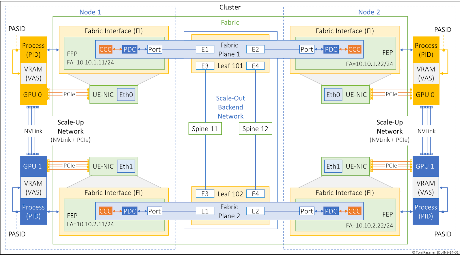
Figure 14-1 depicts a small, two-node parallel computing system, where each node contains two GPUs and UE-capable NIC per GPU. These nodes, along with the Scale-Out Backend Network (Switching Infrastructure), form a cluster. The UEC specification uses the term Fabric Interface (FI) to refer to a UE-capable NIC. In Figure 14-1, all four FIs, together with the leaf and spine switches in the Scale-Out Backend Network, make up the fabric. In this context, the fabric includes all network components: UE-NICs, switching infrastructure, inter-switch links, cabling, and transceivers. One-way delay in Backend Scale-Out Network should be less than 10 µs.

The Scale-Up Network refers to intra-node GPU communication using NVLink and PCIe. Scale-Up Networks can also include short-range interconnects that use a high-speed, low-latency, single-tier (non-CLOS topology) switch—enabling tightly coupled multi-node systems that retain scale-up characteristics. Latency for Scale-Up network should be < 1 µs.

A Fabric Endpoint (FEP) is a logical entity that terminates the UET protocol and is identified by a unique Fabric Address (FA). The UET protocol consists of three key sublayers—the Semantic (SES), Packet Delivery (PDS), and Transport Security (TSS) sublayers—analogous to how a VXLAN Tunnel Endpoint (VTEP) terminates the VXLAN data plane. These sublayers will be discussed in detail in upcoming chapters.

The Packet Delivery Context (PDC), a component of the FEP, is a logical construct responsible for unidirectional packet delivery between two FEPs. The Congestion Control Context (CCC), in turn, manages the transmission rate of traffic exchanged over a given PDC.

The term port refers to the physical port of the UE-capable NIC that connects to a fabric switch. Since multiple FEPs may exist on a single FI—each assigned a unique FA—but the FI may have only one (or two, if dual-homed) physical ports, the FAs of all FEPs on the same FI typically share the same MAC address.

A Fabric Plane is a communication path between two or more Fabric Endpoints (FEPs). In Figure 14-1, two Fabric Planes are shown. Fabric Plane 1 connects FEP 111 and FEP 122 through interfaces E1 and E2 on Leaf Switch 101. Fabric Plane 2 connects FEP 211 and FEP 222 via interfaces E1 and E2 on Leaf Switch 102.

In a RoCEv2-based solution, the Scale-Out Network is referred to as the Backend Network, and the communication paths between processes are called Rails.

The Fabric Interface exposes FEPs to parallel computing processes, which are identified by Process IDs (PIDs). A Virtual Address Space (VAS) represents the memory space allocated and registered to a specific process and is identified by a Process Address Space Identifier (PASID).

Figure 14-1: Ultra Ethernet Terminology.