Thursday, 25 January 2024

BGP EVPN Part IV: MAC-VRF L2RIB Update: Local MAC Address

In Figure 1-3 we have VLAN 10 mapped to EVI/MAC-VRF L2VNI10000. TS-A1 (IP: 192.168.11.12/MAC: 1000.0010.beef) is connected to VLAN10 via Attachment Circuit (AC) Ethernet 1/2, (ifindex: 1a000200). 

Figure 1-3: MAC-VRF: L2RIB Local Learning Process.


Example 1-1 shows the VLAN to L2VNI mapping information. 


Leaf-101# show vlan id 10 vn-segment
VLAN Segment-id
---- -----------
10   10000       

Example 1-1: VLAN to EVPN Instance Mapping Information.


Step-1 and 2: MAC Table Update 


During the startup process, TS-A1 sends a Gratuitous ARP (GARP) message to announce its presence on the network and validate the uniqueness of its IP address. It uses its IP address in the Target IP field (Example 1-2). If another host responds to this unsolicited ARP reply, it indicates a potential IP address conflict. 

Ethernet II, Src: 10:00:00:10:be:ef, Dst: Broadcast (ff:ff:ff:ff:ff:ff)
Address Resolution Protocol (reply/gratuitous ARP)
    Hardware type: Ethernet (1)
    Protocol type: IPv4 (0x0800)
    Hardware size: 6
    Protocol size: 4
    Opcode: reply (2)
    [Is gratuitous: True]
    Sender MAC address: 10:00:00:10:be:ef (10:00:00:10:be:ef)
    Sender IP address: 192.168.11.12
    Target MAC address: Broadcast (ff:ff:ff:ff:ff:ff)
    Target IP address: 192.168.11.12

Example 1-2: Gratuitous ARP from TS-A1.


Leaf-101 learns the MAC address of TS-A1 from the ingress frame and encodes the source MAC address 1000:0010:beef into the VLAN10 MAC address table (Example 1-3). The type is Dynamic, and the egress port (next-hop) is interface Ethernet 1/2. The default MAC address aging time in Cisco Nexus 9000 series switches is 1800 seconds (30 minutes). 


Leaf-101# show system internal l2fwder mac
Legend: 
        * - primary entry, G - Gateway MAC, (R) - Routed MAC, O - Overlay MAC
        age - seconds since last seen,+ - primary entry using vPC Peer-Link,
        (T) - True, (F) - False, C - ControlPlane MAC
   VLAN     MAC Address      Type      age     Secure NTFY Ports
---------+-----------------+--------+---------+------+----+------------------
*    10    1000.0010.beef   dynamic   00:03:43   F     F     Eth1/2

Example 1-3: Leaf-101 MAC Address Table.


Step-3: MAC-VRF’s L2RIB Update

The Layer 2 Forwarder (L2FWDER) component detects the new MAC address in the VLAN 10 Bridge Table. The L2FWDER registers this as a MAC move event, prompting it to program the MAC address reachability information into the Layer 2 Routing Information Base (L2RIB) associated with the MAC-IP VRF of tenant TENANT77. Examples 1-4 show, starting from the bottom, how the L2FWDER component first detects a new MAC address, 1000.0010.beef, associated with VLAN 10 over an Attachment Circuit 0x1a000200 (Ethernet1/2, Example 1-5). It adds a new local MAC route to the topology 10 (L2VNI 10000) with the next-hop interface ID 0x1a000200 (Ethernet1/2).


l2fwder_dbg_ev, 690 l2fwder_l2rib_add_delete_local_mac_routes,
154Adding route  topo-id: 10, macaddr: 1000.0010.beef, nhifindx: 0x1a000200
l2fwder_dbg_ev, 690 l2fwder_l2rib_mac_update,
739MAC move 1000.0010.beef (10) 0x0 -> 0x1a000200

Example 1-4: L2RIB Update by L2FWDER.


Example 1-5 verifies the snmp-ifindex 0x1a000200 mapping to physical interface Ethernet1/2.

Leaf-101# show interface snmp-ifindex | i 0x1a000200
Eth1/2          436208128  (0x1a000200)

Example 1-5: SNMP-ifindex to Interface Mapping Verification.


The examples 1-6 demonstrate the L2FWDER component process. An illustration below details the update events from the L2RIB perspective. The L2RIB receives the MAC route 1000.0010.beef (topology 10) and creates a new MAC route after a MAC mobility check. The route is then added to L2VNI 10000 and marked as a local route (rt_flags=L) with the next-hop interface Ethernet1/2.


Leaf-101# sh system internal l2rib event-history mac | i beef
Rcvd MAC ROUTE msg: (10, 1000.0010.beef), vni 0, admin_dist 0, seq 0, soo 0, 
(10,1000.0010.beef):Mobility check for new rte from prod: 3
(10,1000.0010.beef):Current non-del-pending route local:no, remote:no, linked mac-ip count:1
(10,1000.0010.beef):Clearing routelist flags: Del_Pend, 
(10,1000.0010.beef,3):Is local route. is_mac_remote_at_the_delete: 0
(10,1000.0010.beef,3):MAC route created with seq 0, flags L, (), 
(10,1000.0010.beef,3): soo 0, peerid 0, pc-ifindex 0
(10,1000.0010.beef,3):Encoding MAC best route (ADD, client id 5)
(10,1000.0010.beef,3):vni:10000 rt_flags:L, admin_dist:6, seq_num:0 ecmp_label:0 soo:0(--)
(10,1000.0010.beef,3):res:Regular esi:(F) peerid:0 nve_ifhdl:1224736769 mh_pc_ifidx:0 nh_count:1
(10,1000.0010.beef,3):NH[0]:Eth1/2

Example 1-6: L2RIB from the L2RIB Perspective.

Figure 1-7 shows that the MAC address of TS-A1 is installed into the L2RIB associated with topology 10 (VN segment 10000). The entry is marked as a locally learned route (Prod=Local, Flag=L), with the interface Ethernet 1/2 set as the next hop for the MAC address.


Leaf-101# show l2route evpn mac evi 10
Flags -(Rmac): Router MAC (Stt):Static (L):Local (R):Remote (V):vPC link
(Dup):Duplicate (Spl):Split (Rcv):Recv (AD):Auto-Delete (D):Del Pending
(S):Stale (C):Clear, (Ps):Peer Sync (O):Re-Originated (Nho):NH-Override
(Pf):Permanently-Frozen, (Orp): Orphan
Topology    Mac Address    Prod   Flags         Seq No     Next-Hops
----------- -------------- ------ ------------- ---------- -----------------
10          1000.0010.beef Local  L,            0          Eth1/2

Example 1-7: Updated L2RIB.


Next, L2RIB Update, MAC-IP binding. 


Friday, 19 January 2024

BGP EVPN Part III: BGP EVPN Local Learning Fundamentals

Multi-Protocol BGP (MP-BGP) is a BGP-4 extension that enables BGP speakers to encode Network Layer Reachability Information (NLRI) of various address types, such as IPv4/6, VPNv4, and MAC addresses, into BGP Update messages. MP-BGP features an MP_REACH_NLRI Path-Attribute (PA), which utilizes an Address Family Identifier (AFI) to describe service categories. Subsequent Address Family Identifier (SAFI), in turn, defines the solution used for providing the service. For example, L2VPN (AFI 25) is a primary category for Layer-2 VPN services, and the Ethernet Virtual Private Network (EVPN: SAFI 70) provides the service. Another L2VPN service is Virtual Private LAN Service (VPLS: SAFI 65). The main differences between these two L2VPN services are that only EVPN supports active/active multihoming, has a control-plane-based MAC address learning mechanism, and operates over an IP-routed infrastructure.

EVPN utilizes various Route Types (EVPN RT) to describe the Network Layer Reachability Information (NLRI) associated with Unicast, BUM (Broadcast, Unknown unicast, and Multicast) traffic, as well as ESI Multihoming. The following sections explain how EVPN RT 2 (MAC Advertisement Route) is employed to distribute MAC and IP address information of Tenant Systems enabling the expansion of VLAN over routed infrastructure. 

The Tenant System refers to a host, virtual machine, or an intra-tenant forwarding component attached to one or more Tenant-specific Virtual Networks. Examples of TS forwarding components include firewalls, load balancers, switches, and routers.

TS’s MAC Address Local Processing - Basics

Switch Leaf-101, in Figures 1-2, serves as our Virtual Tunnel Endpoint (VTEP) device, supporting the BGP L2VPN EVPN address family. By configuring an EVPN instance (EVI) on VTEP, we deploy an instance-specific MAC-VRF, a Virtual Routing and Forwarding table for MAC addresses (L2RIB). Each EVI is identified by a Layer-2 Virtual Network Identifier (L2VNI). In the VXLAN header on the data plane, a remote VTEP utilizes L2VNI to describe the EVPN instance to the local VTEP. Besides L2VNI, each EVI has a unique Route Target (RT), an extended community path attribute for import/export policies, and a Route Distinguisher (RD) to facilitate inter-tenant overlapping MAC and IP addresses. 

In Figure 1-2, we have an EVPN Instance (MAC-VRF) that we have given an L2VNI 10000. The RT associated with EVI is AS-specific with auto-derived service-Id (L2VNI) as Local Administrator (AS:L2VNI = 65000:10000). The attached RD, in turn, is auto-derived from the IP address bound to interface NVE1 and VLAN-Id added to the base number 32767 (192.168.100.101:32777).

Tenant System (TS-A1) in Figure 1-2 is connected to VLAN 10 via an Attachment Circuit (AC), Ethernet 1/2 (an AC can be either a physical or logical interface). Leaf-101, serving as a VTEP device, must employ local MAC address learning from the data plane. For instance, when TS-A1 goes live, it may validate the uniqueness of its IP address using Gratuitous ARP (GARP) to check if its IP address has already been assigned to another TS. Leaf-101 then records the source MAC address from the ingress GARP message's Ethernet header into the Bridge Table of VLAN 10. The Next-Hop for the MAC address is AC E1/2. In addition to saving the information into the Bridge Table, Leaf-101 initiates the MAC entry aging timer, which defaults to 1800 seconds (30 minutes).

Once the MAC address information is saved in the Bridge Table, the Layer-2 Forwarder (L2FWDR) component replicates this information into the EVI’s L2RIB  as a Local route. Mapping VLAN to EVI is done under the Layer 2 VLAN configuration. We are using the VLAN-Based Service Interface solution with a one-to-one mapping between VLAN and EVI. So, there is only one VLAN per EVI. 

In addition to MAC address information, the VTEP device, Leaf-101, learns IP address details from the ingress GARP message sent by TS-A1 and stores this information in the tenant-specific ARP table. It is important to note that the tenant must have the VRF Context (IP-VRF) configured. Furthermore, a Layer 3 VLAN interface is necessary for VLAN (Broadcast Domain). In the absence of a Layer 3 VLAN, there will be no ARP table. The Host Mobility Manager (HMM) detects the ARP table update event and subsequently replicates the ARP entry to the tenant-specific local host database. Following this, the HMM updates the L2RIB by binding an IP address to a MAC address and adding information about the L3VNI assigned to IP-VRF to the TS-A1 MAC address entry.

HMM also encodes the IP address of TS-A1 (192.168.11.11/32) into the IP-VRF as a tenant-specific local IP route. It's important to note that host routes are utilized for inter-VN routing and are not advertised as an IP Prefix Route (EVPN RT 5).

Next, Leaf-101 constructs a BGP routing entry in the BGP BGP-Loc RIB describing an NLRI related to TS-A1. Two BGP Route Target (RT) path attributes are assigned to the BGP routing table entry: RT65000:10000 (for MAC-VRF) for MAC addresses and RT65000:10077 (for IP-VRF) for IP addresses. By utilizing these RTs, remote VTEP devices can import the received EVPN NLRI into BGP tables. 

EVI instance with L2VNI 10000 is a member VNI for the interface NVE1. The primary task of the NVE1 interface is to encapsulate egress packets with VXLAN headers and remove encapsulation from ingress frames/packets. The BGP Extended Community Encapsulation type VXLAN (type 8) is configured based on the interface NVE1 settings.

The system MAC, in turn, belongs to VTEP device Leaf-101. But why do we need a system MAC address extended community? VXLAN is a “MAC in IP/UDP” encapsulation model. Since inter-VN packets, routed over an IRB service interface, do not utilize the MAC address of the Tenant System, the NVE’s system MAC address is used as the source MAC address in the inner Ethernet header. Therefore, the IRB service interface must have a Layer 2 VLAN and a non-IP address Layer 3 VLAN interface. This configuration allows the local VTEP to use the system MAC address as the source in the inner Ethernet frame. The remote VTEP, in turn, uses it as a destination MAC address in the inner Ethernet frame.

The MP_REACH_NLRI Path Attribute carries the EVPN Network Layer Reachability Information (NLRI) about TS-A1. The Next-Hop is the IP address of an interface NVE1. EVPN Route Type “MAC Advertisement Route” (RT 2). The Route Distinguisher global administrator is the BGP Router-Id 192.168.77.101, and the local administrator is 32777 (RD: 192.168.77.101:32777). MAC and IP addresses, as well as VNIs, are taken from the L2RIB. From the BGP Loc-RIB, the NLRI information is sent through the BGP policy engine to BGP Adj-RIB-In and sent to BGP peers, Spine switches, which, after processing the BGP received BGP update message, forward information to other VTEP switches.

The upcoming post details the local VTEP operation and explains how the remote VTEP processes the received BGP Update message.


Figure 1-2: BGP EVPN with VXLAN –Building Blocks.

Wednesday, 3 January 2024

BGP EVPN Part II: Network Virtualization Overlay with BGP EVPN and VXLAN - Introduction

In Figure 1-1, we have a routed 3-stage Clos Fabric, where all Inter-Switch links are routed point-to-point layer-3 connections. As explained in previous sections, a switched layer-2 network with an STP control plane allows only one active path per VLAN/Instance and VLAN-based traffic load sharing. Due to the Equal Cost Multi-Path (ECMP) supported by routing protocols, a routed Clos Fabric enables flow-based traffic load balancing using all links from the ingress leaf via the spine layer down to the egress leaf. The convergence time for routing protocols is faster and less disruptive than STP topology change. Besides, a routed Clos Fabric architecture allows horizontal bandwidth scaling. We can increase the overall bandwidth capacity between switches, by adding a new spine switch. Dynamic routing protocols allow standalone and virtualized devices lossless In-Service Software Update (ISSU) by advertising infinite metrics or withdrawing all advertised routes.

But how do we stretch layer-2 segments over layer-3 infrastructure in a Multipoint-to-Multipoint manner, allowing tenant isolation and routing between segments? The answer relies on the Network Virtualization Overlay (NVO3) framework. 

BGP EVPN, as an NVO3 control plane protocol, uses EVPN Route Types (RT) in update messages for identifying the type of advertised EVPN NLRIs (Network Layer Reachability Information). Besides publishing prefix information with RT-5 (IP Prefix Route), BGP EVPN uses RT-2 (MAC-IP advertisement) for publishing hosts’ MAC/IP addresses NLRI. Among these two fundamental route types, BGP EVPN can create a shared delivery tree for layer-2 Broadcast traffic, such as ARP Request messages, without using a Multicast-enabled underlay network. Besides, BGP EVPN allows us to implement a Tenant Routed Multicast (TRM) solution. We can use a vPC for device multihoming, but BGP EVPN has a built-in ESI multihoming option utilizing RT-1 (Ethernet AD Route) and RT-4 (Ethernet Segment Route). This solution uses a proactive control plane learning, where Leaf switches publish reachability information when a hos joins the network.

Virtual Extensible LAN (VXLAN) encapsulation allows switches to add a Layer-2 Virtual Network Identifier (L2VNI) for Intra-VLAN traffic and L3VNI for Tenant-specific/VRF Inter-VLAN connections. The Generic Protocol Extension for VXLAN (VXLAN-GPE) enables leaf switches to add a Group Policy to data packets. 

Finally, adding a new Layer-2 segment to a BGP EVPN fabric requires configuration only in leaf switches. We don’t have to touch Inter-Switch links or spine switches, like we must do in Layer-2 switched infrastructure. 

In the upcoming chapter, we delve deeper into the implementation and advantages of the BGP EVPN with VXLAN data center fabric solution.


Figure 1-1: Routed 3-Stage Clos Fabric with BGP EVPN and VXLAN.

Monday, 1 January 2024

BGP EVPN Part-I: Challenges in Traditional Switched Datacenter Networks

Inefficient Link Utilization

The default Layer 2 Control Plane protocol in Cisco NX-OS is a Rapid Per-VLAN Spanning Tree Plus (Rapid PVST+), which runs 802.1w standard Rapid Spanning Tree Protocol (RSTP) instance per VLAN. Rapid PVST+ builds a VLAN-specific, loop-free Layer 2 data path from the STP root switch to all non-root switches. Spanning Tree Protocol, no matter which mode we use, allows only one active path at a time and blocks all redundant links. One general solution for activating all Inter-switch links is placing an STP root switch for odd and even VLANs into different switches. However, STP allows only a VLAN-based traffic load balancing.


CPU and Memory Usage

After building a loop-free data path, switches running Rapid PVST+ monitor the state of the network by using Spanning Tree instance-based Bridge Protocol Data Units (BPDU). By default, each switch sends instance-based BPDU messages from their designated port in two-second intervals. If we have 2000 VLANs, all switches must process 2000 BPDUs. To reduce CPU and Memory consumption caused by BPDU processing, we can use Multiple Spanning Tree – MSTP (802.1s), where VLANs are associated with Instances. For example, we can attach VLANs 1-999 to one instance and VLANs 1000-1999 to another, reducing the instance count from 2000 to 2. Though the MSTP reduces CPU burden, it does not allow flow-based frame load-balancing. Besides, an MSTP brings an increased complexity, especially when we must connect an MSTP Region to a non-MSTP region.


Bandwidth Scaling

A Multi-Chassis Link Aggregation Group (MLAG) allows the bundling of separate Ethernet links from distinct devices into a unified logical port (Port-Channel). This solution enables a flow-based traffic load sharing. Cisco's solution for NX-OS is a virtual Port Channel (vPC). 

Scaling up a Port-Channel bandwidth requires adding new links to the bundle in both vPC pair switches. For example, to increase the 20 Gbps Port-Channel, we must add a 10 Gbps interface for both vPC pair spine switches and the upstream leaf switch. This link bundling gives us a 40 Gbps logical interface. So, what is the problem with this approach? Let us say that the Port Channel utilization is approximately 30 Gbps. If one of the vPC devices fails, the available Port-Channel bandwidth decreases from 40 Gbps to 20 Gbps. This over-subscription could lead to potential link congestion and packet drops.   


In-Service Software Upgrade

We can remove devices from the data path in the Layer 3 network without disturbing the data plane. For example, Cisco’s vPC enables In-Service Software Upgrade (ISSU) or hardware maintenance tasks using the Graceful Insertion and Removal (GIR) method. We may remove the NX-OS switch from the service using System Maintenance Mode. As a reaction to this mode, the switch advertises its OSPF point-2-point links with infinite metric 65535, withdraws all BGP routes, and shuts down vPC peer-link, keepalive link, and member ports. Besides, in BGP EVPN/VXLAN fabric, the switch also shuts down the loopback interface associated with an NVE interface. However, the process does not disable loopback interfaces used by OSPF and BGP, and OSPF adjacencies and BGP peering stays up. When the device has completed the protocol isolation processes, we can safely do the maintenance tasks without disturbing application traffic. 

This kind of signaling is not supported in the Layer 2 switched networks, and maintenance tasks requiring device removal will cause some level of data flow disruptions.


Flood Reduction

Hosts resolve each other's MAC-IP address-binding information using the Address Resolution Protocol (ARP). ARP Requests are transmitted as Layer 2 Broadcast messages. When switches receive these requests, they learn the requester's MAC address from the source MAC address in the incoming frame. Because of the Broadcast destination MAC address, switches flood ARP requests out of interfaces where the VLAN is permitted. Due to this reactive data plane learning process, all switches must process ARP messages.

When a non-edge port state on a switch transitions from Discarding/Learning to Forwarding, the switch recognizes this change as a Spanning Tree topology event and initiates a TcWhile timer (twice the STP Hello time). During the TcWhile timer duration, the switch sets the Tc (Topology Change) bit in each Bridge Protocol Data Unit (BPDU) message. In response to receiving a BPDU message with the Tc bit set, switches start the TCWhile timer, activate the TC bit in their outgoing BPDU messages, and clear their MAC address tables. This process propagates throughout the switching infrastructure. While hosts may retain the MAC-IP address binding information, switches must re-learn MAC addresses through a flood-and-learn process.


Configuration

Most modern-day applications utilize server virtualization, commonly known as Virtual Machines (VMs). The VM live migration process allows for the seamless transfer of a running VM from one host to another without causing significant downtime or disrupting the services running on that VM. From a network perspective, VM live migration requires the availability of Layer 2 segments and gateways through the data center switches. 

From an operational standpoint, VLANs need to be configured not only on each switch but also on every Inter-Switch link in a switched network. Automatization can help reduce the deployment time and likelihood of configuration errors. However, a notable drawback is the necessity to deploy configuration changes to spine switches as well.


VLAN-Id Limitation

The Layer 2 segmentation with any Spanning Tree Protocol relies on a 12-bit VLAN identifier in 802.1Q tag on the Ethernet frame, giving 2^12 = 4096 unique VLANs. This limitation can pose challenges in environments requiring more VLANs for segmentation.


MAC Address Overlapping

In a multi-tenant environment, where server team administrators are allowed to allocate MAC addresses for application servers manually, there's a risk of MAC address conflicts. Such conflicts can lead to application disruptions and usability issues.

Next, How BGP EVPN with VXLAN Responds to these Challenges.

Wednesday, 22 November 2023

Cisco Intent-Based Networking: Part II - Cisco ISE and Catalyst Center Migration

Cisco Identity Service Engine (ISE) and Catalyst Center Integration

Before you can add Cisco ISE to Catalyst Center’s global network settings as an Authentication, Authorization, and Accounting server (AAA) for clients and manage the Group-Based access policy implemented in Cisco ISE, you must integrate them. 

This post starts by explaining how to activate the pxGrid service on ISE, which it uses for pushing policy changes to Catalyst Center (steps 1a-f). Next, it illustrates the procedure to enable  External RESTful API (ERS) read/write on Cisco ISE to allow external clients to Create, Read, Update, and Delete (CRUD) processes on ISE. Catalyst Center uses ERS for pushing configuration to ISE. After starting the pxGrid service and enabling ERS, this post discusses how to initiate the connection between ISE and Catalyst Center (steps 2a-h and 3a-b). The last part depicts the Group-Based Access Control migration processes (4a-b).

Step-1: Start pxGrid Service and Enabling ERS on ISE

Open the Administrator tab on the main view of Cisco ISE. Then, under the System tab, select the Deployment option. The Deployment Nodes section displays the Cisco ISE Node along with its personas. In Figure 1-3, a standalone ISE Node is comprised of three personas: Policy Admin Node (PAN), Management Node (MnT), and Policy Service Node (PSN). To initiate the pxGrid service, click in the ISE standalone node (1d) and check the pxGrid tick box (1e) in the General Settings window. After saving the changes, pxGrid will be shown in the persona section alongside PAN, PSN, and MnT.

A brief note about Cisco ISE terminology: The term "Node" refers to an ISE node that may have one or multiple personas (PAN, PSN, MnT, pxGrid). These personas define the services provided by the node. For instance, pxGrid facilitates the distribution of context-specific data from Cisco ISE to various network systems, including ISE ecosystem partner systems and different Cisco platforms such as Catalyst Center.

To enable Catalyst Center to push configurations to ISE, activate the ERS in the Settings section under the System tab. 

Step-2: Add Cisco ISE on Catalyst Center

In Catalyst Center, you can access the same configuration window through various methods. In Figure 1-3, we begin the configuration process by clicking the System icon and selecting the Settings option. Then, under the External Services option, choose the Authentication and Policy Servers option. First, enter the server IP and then provide the Shared Secret. It's important to note that the Shared Secret defines the password for the AAA configuration pushed to network devices using the AAA service. The Username and Password fields are credentials utilized for accessing the ISE Graphical User Interface (GUI) and Command Line Interface (CLI). Please note that GUI and CLI passwords need to be the same. Besides, input the Fully Qualified Domain Name (FQDN) and the Subscriber name. After applying these changes, Catalyst Center performs the following actions: 2e) Initiates the CLI and GUI connection to ISE, 2f) Starts the certification import/export process to establish a trusted and secure connection with ISE, 2g) Discovers PAN primary and secondary nodes, as well as pxGrid nodes, and 2h) Connects to the pxGrid service.

To finalize the connection, accept the Catalyst Center connection request in ISE. Navigate to the pxGrid Service tab under the Cisco ISE Administrator tab. In our example, DNAC is a pxGrid client awaiting approval from the ISE admin. Approve the connection by clicking the Approve button.

Step-3: Add Cisco ISE on Catalyst Center

To utilize Catalyst Center as an administration point for Group-Based access control, you need to migrate policies from Cisco ISE. Start the process by selecting the 'Group-Based Access' option under the Policy icon. Then, choose the 'Start Migration' hyperlink. Once the migration is completed, the policy matrix will appear in the Policy tab. From there, you can define micro-segmentation rules between groups on Catalyst Center, which are subsequently pushed to Cisco ISE using REST API. The following section demonstrates how you can add Cisco ISE as AAA services.


Figure 1-3: Integrating Cisco ISE and Catalyst Center.


Sunday, 12 November 2023

Cisco Intent-Based Networking: Part I - Introduction

 Introduction

This chapter introduces Cisco's approach to Intent-based Networking (IBN) through their Centralized SDN Controller, Cisco DNA Center, rebranded as Cisco Catalyst Center (from now on, I am using the abbreviation C3 for Cisco Catalyst Center). We focus on the network green field installation, showing workflows, configuration parameters, and relationships and dependencies between building blocks. The C3 workflow is divided into four main entities: 1) Design, 2) Policy, 3) Provision, and 4) Assurance, each having its own sub-processes. This chapter introduces the Design phase focusing on Network Hierarchy, Network Settings, and Network Profile with Configuration Templates. 

This post deprecates the previous post, "Cisco Intent-Based Networking: Part I, Overview."

Network Hierarchy

Network Hierarchy is a logical structure for organizing network devices. At the root of this hierarchy is the Global Area, where you establish your desired network structure. In our example, the hierarchy consists of four layers: Area (country - Finland), Sub-area (city - Joensuu), Building (JNS01), and Floor (JNS01-FLR01). Areas and Buildings indicate the location, while Floors provide environmental information relevant to wireless networks, such as floor type, measurements, and wall properties.


Network Settings

Network settings define device credentials (CLI, HTTP(S), SNMP, and NETCONF) required for accessing devices during the discovery process. Additionally, network settings describe global configurations (DHCP, DNS, NTP, AAA, and Telemetry) applied to devices during provisioning at a site. We also configure a global IP pool, which we can later break down into site-specific subnets.

In order for you to use the Cisco Identity Service Engine for device/client AAA services (Authentication, Authorization, and Accounting), C3-ISE integration is required. To integrate the Cisco Identity Service Engine with C3, enable the pxGrid persona and External RESTful Service (ERS) in  Cisco ISE. Subsequently, connect C3 to pxGrid as an XMPP client. As the final step, migrate ISE Group-Based Access Control policies to your C3. Through the ISE-C3 integration, you can utilize C3 not only as an AAA server but also for configuring Scalable Group Tag (SGT) policies between groups.


Configuration Templates and Network Profiles

Next, we build a site and device type-specific configuration templates. As a first step, we create a Project, a folder for our templates. In Figure 1-1, we have a Composite template into which we attach two Regular templates. Regular templates include CLI configuration parameters and variables. Then, we create a Profile into which we associate our templates. In Figure 1-1, we have attached the Composite template to the Profile. We make the templates available for devices, which we later provision to the site using a profile-to-site association. Note that we are using Day-N templates. Day-0 templates are for the Plug-and-Play provisioning process.


Figure 1-1: Design – Network Hierarchy, Global Network Settings, and Network Profiles.


Thursday, 5 October 2023

Cisco Intent Based Networking: Part I, Overview

This post introduces Cisco's approach to Intent-based Networking (IBN) through their Centralized SDN Controller, DNA Center, rebranded as Catalyst Center. We focus on the network green field installation, showing workflows, configuration parameters, and relationships and dependencies between building blocks.

Figure 1-1 is divided into three main areas: a) Onboard and Provisioning, b) Network Hierarchy and Global Network Settings, c) and Configuration Templates and Site Profiles. 

We start a green field network deployment by creating a Network Design. In this phase, we first build a Network Hierarchy for our sites. For example, a hierarchy can define Continent/Country/City/Building/Floor structure. Then, we configure global Network Settings. This phase includes both Network and Device Credentials configuration. AAA, DHCP, DNS serves, DNS name, and Time Zone, which are automatically inherited throughout the hierarchy, are part of the Network portion. Device Credentials, in turn, define CLI, SNMP read/write, HTTP(S) read/write username/password, and CLI enable password. The credentials are used later in the Discovery phase.

Next, we build a site and device type-specific configuration templates. As a first step, we create a Project, a folder for our templates. In Figure 1-1, we have a Composite template into which we attach two Regular templates. Regular templates include CLI configuration parameters and variables. Next, we create a Profile into which we associate our template. In Figure 1-1, we have attached the Composite template to the Profile. We make the templates available for devices, which we later provision to the site using a profile-to-site association. Note that we are using Day-N templates. Day-0 templates are for the Plug-and-Play provisioning process.

As a final step, we delve into the device onboarding and provisioning processes. You can discover devices using CDP, LLDP, IP range, or CIDR. Discovery utilizes the device credentials defined in the Design/Network Settings step. The detected devices are listed in the Inventory section, where we can select them and assign them to a site. After adding the device to the site, we can proceed with provisioning. We choose the configuration templates associated with the site to deploy them onto the device. Additionally, any inherited global configurations are applied to the device. 


Figure 1-1: Cisco IBN Deployment - Phase 1 (click the image to enlarge).


The upcoming posts will provide a detailed explanation of these processes.

Sunday, 27 August 2023


Available at Leanpub and Amazon


About This Book

A modern application typically comprises several modules, each assigned specific roles and responsibilities within the system. Application architecture governs the interactions and communications between these modules and users. One prevalent architecture is the three-tier architecture, encompassing the Presentation, Application, and Data tiers. This book explains how you can build a secure and scalable networking environment for your applications running in Microsoft Azure. Besides a basic introduction to Microsoft Azure, the book explains various solutions for Virtual Machines Internet Access, connectivity, security, and scalability perspectives.


Azure Basics: You will learn the hierarchy of Microsoft Azure datacenters, i.e., how a group of physical datacenters forms an Availability Zone within the Azure Region. Besides, you learn how to create a Virtual Network (VNet), divide it into subnets, and deploy Virtual Machines (VM). You will also learn how the subnet in Azure differs from the subnet in traditional networks.


Internet Access: Depending on the role of the application, VMs have different Internet access requirements. Typically, front-end VMs in the presentation tier/DMZ are visible on the Internet, allowing external hosts to initiate connections. VMs in the Application and Data tiers are rarely accessible from the Internet but might require outbound Internet connections. Additionally, VMs within a load balancer backend pool can utilize the load balancer's virtual IP/front-end IP for Internet access. This book explains various ways to enable Internet access, including NAT gateway and load balancer services.

Connectivity: The book explains how to establish bi-directional connections between Virtual Networks in Azure and remote sites using VPN Gateway (VGW) service and ExpressRoute connection. You will also learn VNet peering deployment (point-to-point and hub-and-spoke over VGW) using connection-specific configuration and deployed with a Virtual Network Manager (VNM). This book also has three chapters about Virtual WAN (vWAN), which describes regional and global S2S VPN connections and peered VNet segmentation solutions.


Security: Azure has several ways to protect your VMs from unwanted traffic. VMs are protected with Azure’s stateful firewall, Network Security Group (NSG). Besides, you can secure all VMs within a subnet using subnet-specific NSG. Application Security Group (ASG), in turn, groups VMs into a logical group that you can use as a destination in NSG. You can deploy a global security policy with a Security Admin Configuration (SAC) using Virtual Network Manager (VNM). Among the standard allow/deny rules, VNM enables you to deploy an always-allow policy that overrides NSG rules defined by local administrators. The last chapter of the book introduces Azure Firewall service. Besides using traffic NSGs and Azure FW, you will learn how to use segmentation as a security feature.


Load Balancing Service: The purpose of Azure load balancers service for inbound traffic is to distribute incoming network requests or traffic across multiple virtual machines or instances, ensuring optimal resource utilization and improved availability. Besides, the load balancing service offers outbound Internet access for backend pool members by hiding a source private IP behind the front-end Virtual IP address. The third use case for LBS is to enable active/active Virtual Network Appliance (NVA) design. This book introduces three main building blocks of LBS, an SDN controller (also known as Ananta) in the Control Plane, a load balancer pool (also known as software MUX pool) in the data plane, and a host agent running on a server. This book doesn't just explain the different use cases but introduces the control plane processes focusing on system components' interaction and responsibilities. Additionally, you will learn an LBS's data plane redundancy and packet forwarding model.


Virtual Machine Networking: Virtual Filtering Platform (VFP) is Microsoft’s cloud-scale software switch operating as a virtual forwarding extension within a Hyper-V basic vSwitch. The forwarding logic of the VFP uses a layered policy model based on policy rules on the Match-Action Table (MAT). VFP works on a data plane, while complex control plane operations are handed over to centralized control systems. Accelerated Networking, in turn, reduces the physical host’s CPU burden and provides a higher packet rate with a more predictable jitter by switching the packet using hardware NIC yet still relaying to VFP from the traffic policy perspective. 

The structure of each chapter is consistent. Each chapter begins with an Introduction, which introduces the solution and presents the topology diagram. Following that, you will learn how to deploy the service using the Azure portal. Additionally, several chapters include deployment and verification examples using Azure CLI or Azure PowerShell.


Figure 1 illustrates the various resources and services introduced in the book. While the diagram doesn't explicitly cover Azure networking best practices, it does highlight the relationships between different building blocks. If you're new to Azure networking, the picture might appear complex initially. Nevertheless, by the time you complete the book, it should become thoroughly understandable. 


Table of Contents

Chapter 1: Azure Virtual Network Basics 1
Introduction 1
Geography, Region, and Availability Zone 1
Resource Groups and Resources 2
Create Resource Group with Azure Portal 4
Create VNet with Azure Portal 11
Deploy VNet Azure Resource Manager Templates 18
Pre-Tasks 19
Deployment Template for VNet 21
Deployment Parameters for VNet 26
Deploying Process 29
Summary 36
References 37

Chapter 2: Network Security Groups (NSG) 40
Introduction 40
VM to NSG Association 42
Step-1: Deploy VM vm-Bastion 42
Step-2: SSH connection to VM 56
NSG to Subnet Association 60
Step-1: Create New NSG 61
Step-2: Add an Inbound Security Rule to NSG 62
Step-3: Associate the NSG to Subnet 64
Application Security Group 67
Step-1: Create Application Security Group 67
Step-2: Add a Security Rule into NSG 68
Step-3: Associate VM’s NIC with ASG 69
Step-4: Test Connection 72
Resources View 73
Pricing 77
References 78
Chapter 3: Internet Access with VM-Specific Public IP 80
Introduction 80
Public IP Address for the Internet Access 81
Public IP Allocation Method 82
Stock-Keeping Unit (SKU) 82
Public IP Verification 83
Internet Outbound Traffic Testing 85
Public IP Addresses for Azure Internal Communication 86
References 90

Chapter 4: Virtual Network NAT Service - NAT Gateway 91
Introduction 91
Create Public IP address 92
Create NAT Gateway 95
Basic Settings 96
Outbound IP Address 97
VNet and Subnet Association 98
Deploying 99
Verification 100
Pricing 104
Delete NAT Gateway 105
References 107

Chapter 5: Hybrid Cloud - Site-to-Site VPN 109
Introduction 109
Create GatewaySubnet 110
Create Virtual Network Gateway (VGW) 111
Create Local Gateway (LGW) 119
Create VPN Connection 123
Configure Local Gateway 128
Download Configuration File 128
Configure Local Gateway 133
Verification 134
Data Plane Testing 137
Pricing 138
References 139

Chapter 6: Hybrid Cloud – Site-to-Site VPN with BGP 141
Introduction 141
Enable BGP on VGW 142
Enable BGP on LGW 144
Enable BGP on S2S VPN Connection 146
Configure BGP on LGW 148
Control Plane Verification on VGW 149
Control Plane Verification on LGW 153
References 155
Chapter 7: VNet-to-VNet VPN 157
Introduction 157
VGW Settings 158
Connection Settings 159
Control Plane Verification 163
References 170

Chapter 8: VNet Peering 171
Introduction 171
Deploy VNet Peering 173
Verification 176
VNet Peering 176
Control Plane - BGP 180
The RIB Associated with NIC vm-spoke-2739 182
The RIB Associated with NIC vm-spoke-1214 183
The RIB Associated with NIC vm-front-1415 184
Data Plane Verification 185
Transit VNet – Hub and Spoke Topology 186
Route Propagation 187
Pricing 190
References 191

Chapter 9: Hybrid Cloud - Routing Studies 192
Introduction 192
BGP Operation 194
Routing Process: on-Prem DC Subnet 10.11.11.0/24 196
Routing Process: VNet CIDR 10.0.0.0/16 203
Data Plane Test Between on-prem DC and Azure 206
Azure Internal Data Plane Verification 206
References 207
Chapter 10 - Appendix A: On-Prem DC – BGP Configuration 208
Lgw-dc1 208
Lgw-dc2 209
Leaf-01 209
Chapter 10 - Appendix B: Azure – BGP Configuration 210
Lgw-dc1 JSON View 210
Lgw-dc2 JSON View 210
Vgw-hub1 JSON View 211
Vgw-hub2 JSON View 212
Chapter 10: Virtual WAN Part 1 - S2S VPN and VNet Connections 214
Introduction 214
Create Virtual WAN (vWAN) 216
Create Virtual Hub and S2S VPN GW 219
Verifying S2S VPN Gateway 224
Create VPN Site 227
VPN site to vHub connection 233
Configure the Remote Site Edge Device 239
VNet to vHub connection 245
Control Plane verification 249
VNet Route Table 249
Virtual Hub Route Table 251
VPN Gateway Routing 251
Branch Control Plane 254
Data Plane verification 256
Pricing 257
References 258
Chapter 11 - Appendix A: Swe-Branch Configuration 259

Chapter 11: Virtual WAN Part 2 –VNet Segmentation 261
Introduction 261
Default Route Table 262
Create New Route Table 266
Control Plane Verification 271
Data Plane Testing 276
References 277

Chapter 12: Virtual WAN Part III - Global Transit Network 279
Introduction 279
Create a New vHub: vhub-ger 280
Create a New VPN Site: ger-branch 281
Control Plane verification 283
vHub Effective Routes 284
vNIC Effective Routes 285
Branch Site Routing 287
BGP Multipathing 289
Data Plane verification 290
Intra-Region Branch-to-VNet 290
Inter-Region Branch-to-VNet (Branch-to-Hub-to-Hub-Vnet) 292
Inter-Region Branch-to-Branch (Branch-to-Hub-to-Hub-Branch) 293
Intra-Region VNet-to-VNet 294
Inter-Region VNet-to-VNet (VNet-to-Hub-to-Hub-Vnet) 295
References 296
Chapter 13 - Appendix A: Ger-Branch Configuration 297

Chapter 13: ExpressRoute 301
Introduction 301
Create a New ExpressRoute Circuit 304
ERP Circuit Provision 307
Configure eBGP Peering with MSEE 310
Connect VNet to ExpressRoute Circuit 313
Create GatewaySubnet 313
Configure ExpressRoute Gateway 314
Connect VNet to Circuit 315
Appendix A. CE-Bailey Cfg and Show Commands 316
References 317

Chapter 14: Azure VM networking – Virtual Filtering Platform 319
Introduction 319
Hyper-V Extensible Virtual Switch 320
Virtual Filtering Platform - VFP 320
Policy Programming to VFP 323
Accelerated Networking 324
Packet Walk 326
Enabling Accelerated Networking 327
Verification 328
References 331

Chapter 15: NVA Part I - NVA Between East-West Subnets 333
Introduction 333
Default Routing in Virtual Network 333
Route Traffic through the Network Virtual Appliance (NVA) 337
Create Route Table with Azure CLI 338
Add Routing Entry to Route Table 339
Create Route Table with Azure Portal 340
Add Routing Entry to Route Table 341
Associate Route Table with Subnet with Azure CLI 342
Associate Route Table with Subnet with Azure Portal 343
Enable IP Forwarding on NVA’s vNICs with Azure CLI 345
Enable IP Forwarding on NVA’s vNICs with Azure Portal 347
Enable IP Forwarding on Linux NVA 348
Data Plane testing 349
Appendix A – Chapter 15 352
Add a new vNIC to Virtual Machine 352
References 353
Chapter 16: NVA Part II - Internet Access with a single NVA 355
Introduction 355
Packet Walk 357
Deployment 359
Linux NVA 359
IP Forwarding on vNIC 360
Data Plane verification 361
References 363

Chapter 17: NVA Redundancy with Public Load Balancer 364
Introduction 364
Load balancer Configuration using Azure Portal 366
Basic Information 367
Frontend IP 369
Backend Pool 371
Inbound Rule 375
NVA Configuration 380
Enable IP Forwarding on NIC 380
Enable IP Forwarding on Linux NVA 381
Configuring destination NAT on Linux 382
Configuring source NAT on Linux 383
Packet Walk 385
References 388

Chapter 18: NVA Redundancy with ILB Spoke-to-Spoke VNet 390
Introduction 390
Internal Load Balancer’s Settings 392
Frontend IP Address 392
Backend Pool 393
Health Probes 393
Inbound Rule 394
VNet Peering 395
User Defined Routing 397
Data Plane Test 401
Verification 402
Failover Test 404
References 406

Chapter 19: NVA Redundancy with ILB, On-prem to Spoke VNet 407
Introduction 407
Packet Walk: SSH Session Initiation – TCP SYN 408
Packet Walk: SSH Session Initiation – TCP SYN-ACK 411
Configuration and Verification 413
Data Plane Testing Using Ping 419
References 421

Chapter 20: Cloud Scale Load Balancing 423
Introduction 423
Management & Control Plane – External Connections 424
Data Plane - External Connections 426
Data Plane and Control Plane for Outbound Traffic 428
Fast Path 430
References 433

Chapter 21: Virtual Network Manager - VNet Peering 434
Introduction 434
Create Virtual Network Manager 435
Create Network Group 439
Create Connectivity Configuration 444
Deploy Connectivity Configuration 450
Add VNets Dynamically to Network Group 456
Verification 460
Delete Policy 462
Pricing 466
References 467

Chapter 22: Network Manager and Security 469
Introduction 469
Create Security Admin Configuration 472
Create SAC Rule Collection 473
Deploy Security Admin Configuration 476
Security Admin Rules Processing 479
Verification 480
References 481

Chapter 23: Azure Firewall 482
Introduction 482
Create Azure Firewall 483
Define Firewall Policy Rule 490
Route Traffic to Firewall 492
Data Plane Testing 495
References 496

Tuesday, 13 June 2023

NVA Part V: NVA Redundancy with Azure Internal Load Balancer - On-Prem Connec

 Introduction


In Chapter Five, we deployed an internal load balancer (ILB) in the vnet-hub. It was attached to the subnet 10.0.0.0/24, where it obtained the frontend IP (FIP) 10.0.1.6. Next, we created a backend pool and associated our NVAs with it. Finally, we bound the frontend IP 10.0.1.6 to the backend pool to complete the ILB setup.


Next, in vnet-spoke1, we created a route table called rt-spoke1. This route table contained a user-defined route (UDR) for 10.2.0.0/24 (vnet-spoke2) with the next-hop set as 10.0.1.6. We attached this route table to the subnet 10.1.0.0/24. Similarly, in vnet-spoke2, we implemented a user-defined route for 10.1.0.0/24 (vnet-spoke1). By configuring these UDRs, we ensured that the spoke-to-spoke traffic would pass through the ILB and one of the NVAs on vnet-hub. Note that in this design, the Virtual Network Gateway is not required for spoke-to-spoke traffic.


In this chapter, we will add a Virtual Network Gateway (VGW) into the topology and establish an IPsec VPN connection between the on-premises network edge router and VGW. Additionally, we will deploy a new route table called "rt-gw-snet" where we add routing entries to the spoke VNets with the next-hop IP address 10.0.1.6 (ILB's frontend IP). Besides, we will add a routing entry 10.3.0.0/16 > 10.0.1.6 into the existing route tables on vnet-spoke-1 and vnet-spoke-2 (not shown in figure 6-1). This configuration will ensure that the spoke to spoke and spoke to on-prem flows are directed through one of the Network Virtual Appliances (NVAs) via ILB. The NVAs use the default route table, where the VGW propagates all the routes learned from VPN peers. However, we do not propagate routes from the default route table into the "rt-gw-snet" and "rt-prod-1" route tables. To enable the spoke VNets to use the VGW on the hub VNet, we allow it in VNet peering configurations.


  1. The administrator of the mgmt-pc opens an SSH session to vm-prod-1. The connection initiation begins with the TCP three-way handshake. The TCP SYN message is transmitted over the VPN connection to the Virtual Gateway (VGW) located on the vnet-hub. Upon receiving the message, the VGW first decrypts it and performs a routing lookup. The destination IP address, 10.1.0.4, matches the highlighted routing entry in the route table rt-gw-snet.
  2. The VGW determines the location (the IP address of the hosting server) of 10.1.0.6, encapsulates the message with tunnel headers, and forwards it to an Internal Load Balancer (ILB) using the destination IP address 10.1.0.6 in the tunnel header.
  3. The Internal Load Balancer receives the TCP SYN message. As the destination IP address in the tunnel header matches one of its frontend IPs, the ILB decapsulates the packet. It then checks which backend pool (BEP) is associated with the frontend IP (FIP) 10.0.1.6 to determine to which VMs it can forward the TCP SYN message. Using a hash algorithm (in our example, the 5-tuple), the ILB selects a VM from the backend pool members, in this case, NVA2. The ILB performs a location lookup for the IP address 10.1.0.5, encapsulates the TCP SYN message with tunnel headers, and finally sends it to NVA2.
  4. The message reaches the hosting server of NVA2, which removes the encapsulation since the destination IP in the tunnel header belongs to itself. Based on the Syn flag set in the TCP header, the packet is identified as the first packet of the flow. Since this is the initial packet of the flow, there is no flow entry programmed into the Generic Flow Table (GFT) related to this connection. The parser component generates a metadata file from the L3 and L4 headers of the message, which then is processed by the Virtual Filtering Platform (VFP) layers associated with NVA2. Following the VFP processing, the TCP SYN message is passed to NVA2, and the GFT is updated with flow information and associated actions (Allow and Encapsulation instructions). Besides, the VFP process creates a corresponding entry for the return packets into the GFT (reversed source and destination IPs and ports). Please refer to the first chapter for more detailed information on VFP processes.
  5. We do not have any pre-routing or post-routing policies configured on either NVA. As a result, NVA2 simply routes the traffic out of the eth0 interface based on its routing table. The ingress TCP SYN message has already been processed by the VFP layers, and the GFT has been updated accordingly. Consequently, the egress packet can be forwarded based on the GFT without the need for additional processing by the VFP layers.
  6. Subsequently, the encapsulated TCP SYN message is transmitted over VNet peering to vm-prod-1, located on vnet-spoke-1. Upon reaching the hosting server of vm-prod-1, the packet is processed in a similar manner as we observed with NVA. The encapsulation is removed, and the packet undergoes the same VFP processing steps as before.


Figure 6-1: ILB Example Topology.

Tuesday, 6 June 2023

NVA Part IV: NVA Redundancy with Azure Internal Load Balancer

Introduction

To achieve active/active redundancy for a Network Virtual Appliance (NVA) in a Hub-and-Spoke VNet design, we can utilize an Internal Load Balancer (ILB) to enable Spoke-to-Spoke traffic.

Figure 5-1 illustrates our example topology, which consists of a vnet-hub and spoke VNets. The ILB is associated with the subnet 10.0.1.0/24, where we allocate a Frontend IP address (FIP) using dynamic or static methods. Unlike a public load balancer's inbound rules, we can choose the High-Availability (HA) ports option to load balance all TCP and UDP flows. The backend pool and health probe configurations remain the same as those used with a Public Load Balancer (PLB).

From the NVA perspective, the configuration is straightforward. We enable IP forwarding in the Linux kernel and virtual NIC but not pre-routing (destination NAT). We can use Post-routing policies (source NAT) if we want to hide real IP addresses or if symmetric traffic paths are required. To route egress traffic from spoke sites to the NVAs via the ILB, we create subnet-specific route tables in the spoke VNets. The reason why the "rt-spoke1" route table has an entry "10.2.0.0/24 > 10.0.1.6 (ILB)" is that vm-prod-1 has a public IP address used for external access. If we were to set the default route, as we have in the subnet 10.2.0.0/24 in "vnet-spoke2", the external connection would fail.

Figure 5-1: ILB Example Topology.

Saturday, 20 May 2023

NVA Part III: NVA Redundancy – Connection from the Internet

This chapter is the first part of a series on Azure's highly available Network Virtual Appliance (NVA) solutions. It explains how we can use load balancers to achieve active/active NVA redundancy for connections initiated from the Internet.

In Figure 4-1, Virtual Machine (VM) vm-prod-1 uses the load balancer's Frontend IP address 20.240.9.27 to publish an application (SSH connection) to the Internet. Vm-prod-1 is located behind an active/active NVA FW cluster. Vm-prod-1 and NVAs have vNICs attached to the subnet 10.0.2.0/24.

Both NVAs have identical Pre- and Post-routing policies. If the ingress packet's destination IP address is 20.240.9.27 (load balancer's Frontend IP) and the transport layer protocol is TCP, the policy changes the destination IP address to 10.0.2.6 (vm-prod-1). Additionally, before routing the packet through the Ethernet 1 interface, the Post-routing policy replaces the original source IP with the IP address of the egress interface Eth1.

The second vNICs of the NVAs are connected to the subnet 10.0.1.0/24. We have associated these vNICs with the load balancer's backend pool. The Inbound rule binds the Frontend IP address to the Backend pool and defines the load-sharing policies. In our example, the packets of SSH connections from the remote host to the Frontend IP are distributed between NVA1 and NVA2. Moreover, an Inbound rule determines the Health Probe policy associated with the Inbound rule.

Note! Using a single VNet design eliminates the need to define static routes in the subnet-specific route table and the VM's Linux kernel. This solution is suitable for small-scale implementations. However, the Hub-and-Spoke VNet topology offers simplified network management, enhanced security, scalability, performance, and hybrid connectivity. I will explain how to achieve NVA redundancy in the Hub-and-Spoke VNet topology in upcoming chapters.


Figure 4-1: Example Diagram. 

Tuesday, 11 April 2023

NVA Part II - Internet Access with a single NVA

Introduction

In the previous chapter, you learned how to route east-west traffic through the Network Virtual Appliance (NVA) using subnet-specific route tables with User Defined Routes (UDR). This chapter introduces how to route north-south traffic between the Internet and your Azure Virtual Network through the NVA.

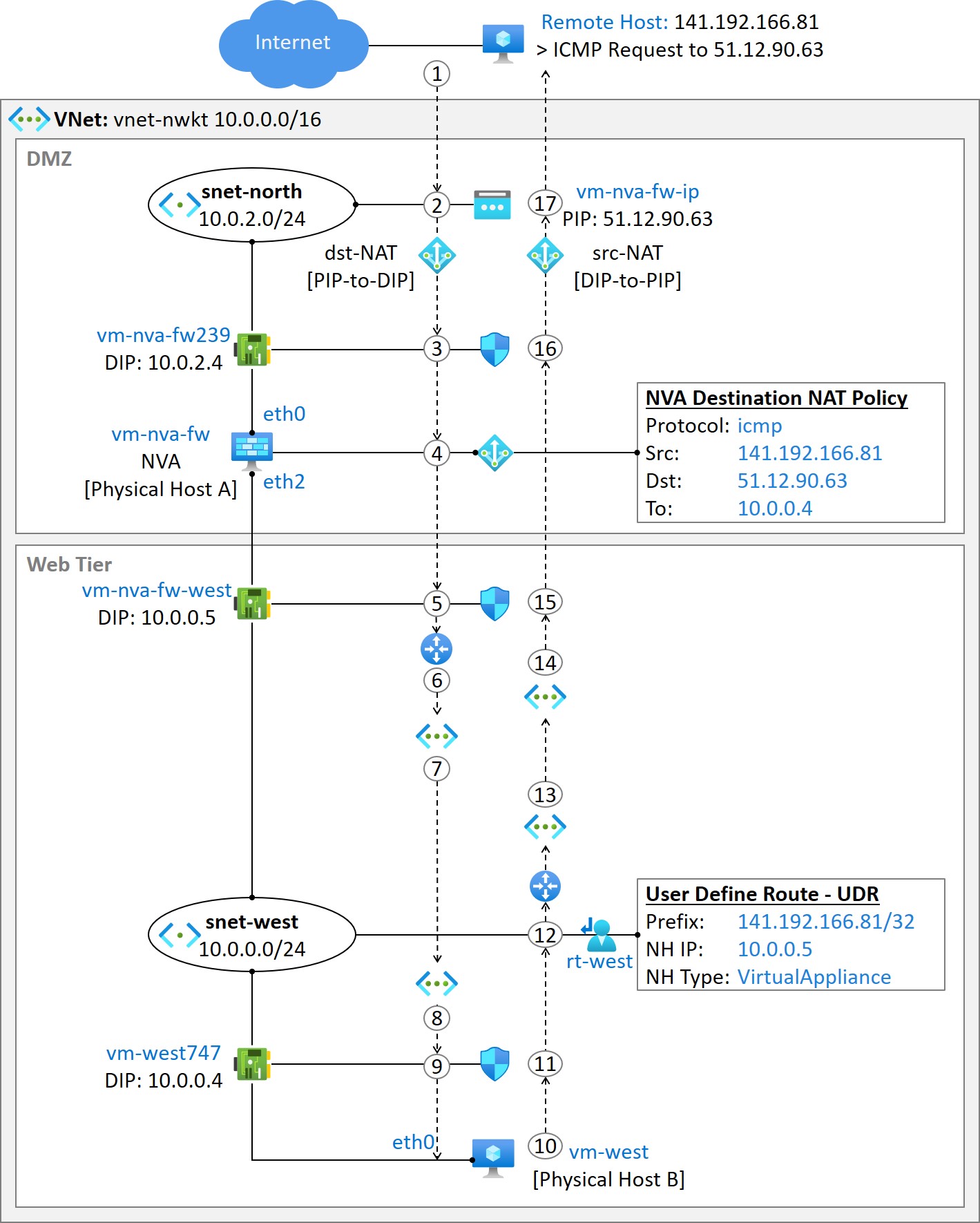
Figure 3-1 depicts our VNet setup, which includes DMZ and Web Tier zones. The NVA, vm-nva-fw, is connected to subnet snet-north (10.0.2.0/24) in the DMZ via a vNIC with Direct IP (DIP) 10.0.2.4. We've also assigned a public IP address, 51.12.90.63, to this vNIC. The second vNIC is connected to subnet snet-west (10.0.0.0/24) in the Web Tier, with DIP 10.0.0.5. We have enabled IP Forwarding in both vNICs and Linux kernel. We are using Network Security Groups (NSGs) for filtering north-south traffic.

Our web server, vm-west, has a vNIC with DIP 10.0.0.4 that is connected to the subnet snet-west in the Web Tier. We have associated the route table to the subnet with the UDR, which forwards traffic to destination IP 141.192.166.81 (remote host) to NVA. To publish the web server to the internet, we've used the public IP of NVA. 

On the NVA, we have configured a Destination NAT rule which rewrites the destination IP address to 10.0.0.4 to packets with the source IP address 141.192.166.81 and protocol ICMP. To simulate an http connection, we're using ICMP requests from a remote host.


Figure 3-1: Example Diagram and.

Monday, 3 April 2023

Routing in Azure Subnets

Introduction

Subnets, aka Virtual Local Area Networks (VLANs) in traditional networking, are Layer-2 broadcast domains that enable attached workloads to communicate without crossing a Layer-3 boundary, the subnet Gateway. Hosts sharing the same subnet resolve each other’s MAC-IP address binding using Address Resolution Protocol, which relays on Broadcast messages. That is why we often use the Failure domain definition with subnets. We can spread subnets between physical devices over Layer-2 links using VLAN tagging, defined in the IEEE 802.1Q standard. Besides, tunnel encapsulation solutions supporting tenant/context identifier enables us to extend subnets over Layer-3 infrastructure. Virtual eXtensible LAN (VXLAN) using VXLAN Network Identifier (VNI) and Network Virtualization using Generic Route Encapsulation (NVGRE) using Tenant Network ID (TNI) are examples of Network Virtualization Over Layer 3 (NVO) solutions. If you have to spread the subnet over MPLS enabled network, you can choose to implement Virtual Private LAN (VPLS) Service or Virtual Private Wire Service (VPWS), among the other solutions.  

In Azure, the concept of a subnet is different. You can think about it as a logical domain within a Virtual Network (VNet), where attached VMs share the same IP address space and use the same shared routing policies. Broadcast and Multicast traffic is not natively supported in Azure VNet. However, you can use a cloudSwXtch VM image from swXtch.io to build a Multicast-enabled overlay network within VNet. 

Default Routing in Virtual Network

This section demonstrates how the routing between subnets within the same Virtual Network (VNet) works by default. Figure 2-1 illustrates our example Azure VNet setup where we have deployed two subnets. The interface eth0 of vm-west and interface eth1 of vm-nva-fw are attached to subnet snet-west (10.0.0.0/24), while interface eth2 of vm-nva-fw and interface eth0 of vm-west is connected to subnet snet-east (10.0.1.0/24). All three VMs use the VNet default routing policy, which routes Intra-VNet data flows directly between the source and destination endpoint, regardless of which subnets they are connected to. Besides, the Network Security Groups (NSGs) associated with vNICs share the same default security policies, which allow inbound and outbound Intra-VNet data flows, InBound flows from the Load Balancer, and OutBound Internet connections. 

Now let’s look at what happens when vm-west (DIP: 10.0.0.4) pings vm-west (DIP: 10.0.1.4), recapping the operation of VFP. Note that Accelerated Networking (AccelNet) is enabled in neither VMs.

  1. The VM vm-west sends an ICMP Request message to vm-east. The packet arrives at the Virtual Filtering Platform (VFP) for processing. Since this is the first packet of the flow, the Flow Identifier and associated Actions are not in the Unified Flow Table (UFT). The Parser component extracts the 5-tuple header information (source IP, source port, destination IP, destination port, and transport protocol) as metadata from the original packet. The metadata is then processed in each VFP layer to generate a flow-based entry in the UFT.
  2. The destination IP address matches the Network Security Group's (NSG) default outbound rule, which allows Intra-VNet flows. Then the metadata is passed on to the routing process. Since we haven't yet deployed subnet-specific route tables, the result of the next-hop route lookup is 3.3.3.3, the Provider Address (PA) of Host-C.
  3. Intra-VNet connections use private IP addresses (DIP-Direct IP), and the VFP process bypasses the NAT layer. The VNet layer, responsible for encapsulation/decapsulation, constructs tunnel headers (IP/UDP/VXLAN). It creates the outer IP address with the source IP 1.1.1.1 (Host-A) and destination IP 3.3.3.3 (Host-C), resolved by the Routing layer. Besides, it adds Virtual Network Identifier (VNI) into the VXLAN header.
  4. After each layer has processed the metadata, the result is encoded to Unified Flow Table (UFT) with Flow-Id with push action (Encapsulation). 
  5. The Header Transposition engine (HT) modifies the original packet based on the UFT actions. It adds tunnel headers leaving all original header information intact. Finally, the modified packet is transmitted to the upstream switch. The subsequent packets are forwarded based on the UFT.
  6. The Azure switching infra forwards the packet based on the destination IP address on the outer IP header (tunnel header).
  7. The VFP on Host-C processes the ingress ICMP Request message in the same manner as VFP in Host-A but in reversed order starting with decapsulation in the VNet layer.

Figure 2-1: Example Topology Diagram.

Wednesday, 22 March 2023

Chapter 1: Azure VM networking – Virtual Filtering Platform and Accelerated Networking

 Note! This post is under the technical review

Introduction


Virtual Filtering Platform (VFP) is Microsoft’s cloud-scale software switch operating as a virtual forwarding extension within a Hyper-V basic vSwitch. The forwarding logic of the VFP uses a layered policy model based on policy rules on Match-Action Table (MAT). VFP works on a data plane, while complex control plane operations are handed over to centralized control systems. The VFP includes several layers, including VNET, NAT, ACL, and Metering layers, each with dedicated controllers that program policy rules to the MAT using southbound APIs. The first packet of the inbound/outbound data flow is processed by VFP. The process updates match-action table entries in each layer, which then are copied into the Unified Flow Table (UFT). Subsequent packets are then switched based on the flow-based action in UFT. However, if the Virtual Machine is not using Accelerated Networking (AccelNet), all packets are still forwarded over the software switch, which requires CPU cycles. Accelerated Networking reduces the host’s CPU burden and provides a higher packet rate with a more predictable jitter by switching the packet using hardware NIC yet still relaying to VFP from the traffic policy perspective.


Hyper-V Extensible Virtual Switch


Microsoft’s extensible vSwitch running on Hyper-V operates as a Networking Virtualization Service Provider (NetVSP) for Virtual Machine. VMs, in turn, are Network Virtualization Service Consumers (NetVSP). When a VM starts, it requests the Hyper-V virtualization stack to connect to the vSwitch. The virtualization stack creates a virtual Network Interface (vNIC) for the VM and associates it with the vSwitch. The vNIC is presented to the VM as a physical network adapter. The communication channel between VM and vSwitch uses a synthetic data path Virtual Machine Bus (VMBus), which provides a standardized interface for VMs to access physical resources on the host machine. It helps ensure that virtual machines have consistent performance and can access resources in a secure and isolated manner. 


Virtual Filtering Platform - VFP


A Virtual Filtering Platform (VFP) is Microsoft’s cloud-scale virtual switch operating as a virtual forwarding extension within a Hyper-V basic vSwitch. VFP sits in the data path between virtual ports facing the virtual machines and default vPort associated with physical NIC. VFP uses VM’s vPort-specific layers for filtering traffic to and from VM. A layer in the VFP is a Match-Action Table (MAT) containing policy rules programmed by independent, centralized controllers. The packet is processed through the VFP layers if it’s an exception packet, i.e., no Unified Flow entry (UF) in the Unified Flow Table (UFT), or if it’s the first packet of the flow (TCP SYN packet). When a Virtual Machine initiates a new connection, the first packet of the data flow is stored in the Received Queue (RxQ). The Parser component on VFP then takes the L2 (Ethernet), L3 (IP), and L4 (Protocol) header information as metadata, which is then processed through the layer policies in each VFP layer. The VFP layers involved in packet processing depend on the flow destination and the Azure services associated with the source/destination VM. 

VNET-to-Internet traffic from with VM using a Public IP


The metering layer measures traffic for billing. It is the first layer for VM’s outgoing traffic and the last layer for incoming traffic, i.e., it processes only the original ingress/egress packets ignoring tunnel headers and other header modifications (Azure does not charge you for overhead bytes caused by the tunnel encapsulation). Next, the ACL layer runs the metadata through the NSG policy statements. If the source/destination IP addresses (L3 header group) and protocol, source/destination ports (L4 header group) match one of the allowing policy rules, the traffic is permitted (action#1: Allow). After ACL layer processing, the routing process intercepts the metadata. Because the destination IP address in the L3 header group matches only with the default route (0.0.0.0/0, next-hop Internet), the metadata is handed over to Server Load Balancing/Network Address Translation (SLB/NAT) layer. In this example, a public IP is associated with VM’s vNIC, so the SLB/NAT layer translates the private source IP to the public IP (action#2: Source NAT). The VNet layer is bypassed if both source and destination IP addresses are from the public IP space. When the metadata is processed by each layer, the results are programmed into the Unified Flow Table (UFT). Each flow is identified with a unique Unified Flow Identifier (UFID) - hash value calculated from the flow-based 5-tuple (source/destination IP, Protocol, Source Port, Destination Port). The UFID is also associated with the actions Allow and Source NAT. The Header Transposition (HT) engine then takes the original packet from the RxQ and modifies its L2/L3/L4 header groups as described in the UFT. It changes the source private IP to public IP (Modify) and moves the packet to TxQ. The subsequent packets of the flow are modified by the HT engine based on the existing UFT entry without running related metadata through the VFP layers (slow-path to fast-path switchover). 

Besides the outbound flow entry, the VFP layer processes generate an inbound flow entry for the same connection but with reversed 5-tuple (source/destination addresses and protocol ports in reversed order) and actions (destination NAT instead of source NAT). These outbound and inbound flows are then paired and seen as a connection, enabling the Flow State Tracking process where inactive connections can be deleted from the UFT. For example, the Flow State Machine tracks the TCP RST flags. Let’s say that the destination endpoint sets the TCP RST flags to the L4 header. The TCP state machine notices it and removes the inbound flow together with its paired outbound flow from the UFT. Besides, the TCP state machine tracks the TCP FIN/FIN ACK flags and TIME_WAIT state (after TCP FIN. The connection is kept alive for max. 2 x Max Segment Lifetime to wait if there are delayed/retransmitted packets).


Intra-VNet traffic


The Metering and ACL layers on VFP process inbound/outbound flows for Intra-VNet connections in the same manner as VNet-Internet traffic. When the routing process notices that the destination Direct IP address (Customer Address space) is within the VNet CIDR range, the NAT layer is bypassed. The reason is that Intra-VNet flows use private Direct IP addresses as source and destination addresses. The Host Agent responsible for VNet layer operations, then examines the destination IP address from the L3 header group. Because this is the first packet of the flow, there is no information about the destination DIP-to-physical host mapping (location information) in the cache table. The VNet layer is responsible for providing tunnel headers to Intra-VNet traffic, so the Host Agent requests the location information from the centralized control plane. After getting the reply, it creates a MAT entry where the action part defines tunnel headers (push action). After the metadata is processed, the result is programmed into Unified Flow Table. As a result, the Header Transposition engine takes the original packet from the Received Queue, adds a tunnel header, and moves the packet to Transmit Queue.

Figure 1-1: Azure Host-Based SDN Building Blocks.

Thursday, 23 February 2023

Azure Networking Fundamentals: Virtual WAN Part 2 - VNet Segmentation

VNets and VPN/ExpressRoute connections are associated with vHub’s Default Route Table, which allows both VNet-to-VNet and VNet-to-Remote Site IP connectivity. This chapter explains how we can isolate vnet-swe3 from vnet-swe1 and vnet-swe2 using VNet-specific vHub Route Tables (RT), still allowing VNet-to-VPN Site connection. As a first step, we create a Route Table rt-swe12 to which we associate VNets vnet-swe1 and vnet-swe2. Next, we deploy a Route Table rt-swe3 for vnet-swe3. Then we propagate routes from these RTs to Default RT but not from rt-swe12 to rt-swe3 and vice versa. Our VPN Gateway is associated with the Default RT, and the route to remote site subnet 10.11.11.0/24 is installed into the Default RT. To achieve bi-directional IP connectivity, we also propagate routes from the Default RT to rt-swe-12 and rt-swe3. As the last step, we verify both Control Plane operation and Data Plane connections. 


Figure 12-1: Virtual Network Segmentation.

Sunday, 5 February 2023

Azure Networking Fundamentals: Virtual WAN Part 1 - S2S VPN and VNet Connections

 This chapter introduces Azure Virtual WAN (vWAN) service. It offers a single deployment, management, and monitoring pane for connectivity services such as Inter-VNet, Site-to-Site VPN, and Express Route. In this chapter, we are focusing on S2S VPN and VNet connections. The Site-to-Site VPN solutions in vWAN differ from the traditional model, where we create resources as an individual components. In this solution, we only deploy a vWAN resource and manage everything else through its management view. Figure 11-1 illustrates our example topology and deployment order. The first step is to implement a vWAN resource. Then we deploy a vHub. It is an Azure-managed VNet to which we assign a CIDR, just like we do with the traditional VNet. We can deploy a vHub as an empty VNet without associating any connection. A vHub deployment process launches a pair of redundant routers, which exchange reachability information with the VNet Gateway router and VGW instances using BGP. We intend to allow Inter-VNet data flows between vnet-swe1, vnet-swe2, and Branch-to-VNet traffic. For Site-to-Site VPN, we deploy VPN Gateway (VGW) into vHub. The VGW started in the vHub creates two instances, instance0, and instance1, in active/active mode. We don’t deploy a GatewaySubnet for VGW because Azure handles subnetting and assigns public and Private IP addresses to instances. Besides, Azure starts a vHub-specific BGP process and allocates a BGP ASN 65515 to the VGW regardless of the selected S2S routing model (static or dynamic). Note that when we connect VNets and branch site to vHub, the Hub Router exchanges routing information with VNet’s GWs and VGW instance using BGP. After the vHub and VGW deployment, we configure VPN site parameters such as IPsec tunnel endpoint IP address, BGP ASN, and peering IP address for the branch device. Then we connect VPN Site to vHub and download the remote device configuration file. The file format is JSON and presents the values/parameters for Site-to-Site VPN and BGP peering but not the device-specific configuration. As a last deployment step, we connect VNets to vHub. The VGW in vHub is associated with a default Route Table (RT), and VNets are associated with none by default. During the connection setup, we need to associate VNets also to default RT. When everything is in place, we verify that each component has the necessary routing information and that the IP connectivity is ok.

Figure 11-1: vWAN Diagram.

Thursday, 2 February 2023

Azure Networking Fundamentals: VNET Peering

Comment: Here is a part of the introduction section of the eight chapter of my Azure Networking Fundamentals book. I will also publish other chapters' introduction sections soon so you can see if the book is for you. The book is available at Leanpub and Amazon (links on the right pane).

This chapter introduces an Azure VNet Peering solution. VNet peering creates bidirectional IP connections between peered VNets. VNet peering links can be established within and across Azure regions and between VNets under the different Azure subscriptions or tenants. The unencrypted data path over peer links stays within Azure's private infrastructure. Consider a software-level solution (or use VGW) if your security policy requires data path encryption. There is no bandwidth limitation in VNet Peering like in VGW, where BW is based on SKU. From the VM perspective, VNet peering gives seamless network performance (bandwidth, latency, delay, and jitter) for Inter-VNet and Intra-VNet traffic. Unlike the VGW solution, VNet peering is a non-transitive solution, the routing information learned from one VNet peer is not advertised to another VNet peer. However, we can permit peered VNets (Spokes) to use local VGW (Hub) and route Spoke-to-Spoke data by using a subnet-specific route table (chapter 9 explains the concept in detail). Note that by deploying a VNet peering, we create a bidirectional, always-on IP data path between VNets. However, we can prevent traffic from crossing the link if needed without deleting the peering. Azure uses Virtual Network Service Tags for VNet peering traffic policy.

Figure 8-1 shows our example topology. We create a VNet Peering between vnet-spoke-2 and vnet-nsg-rt-swedencentral. Besides the Inter-VNet connection, our solution allows vnet-spoke-2 to use vnet-nsg-rt-swedencentral as a transit VNet to other peered VNets (which we don’t have in this example). We also permit IP connection to/from vnet-spoke-2 to vnet-spoke-1 and on-prem location by authorizing vnet-spoke-2 to use vgw-nwkt as a transit gateway.

Figure 8-1: VNet Peering Example Diagram.